


Identifying the Inverter
Refer to the sticker on the inverter that specifies its Serial Number and its Electrical
Ratings. Provide the serial number when contacting SolarEdge support. The serial
number is also required when opening a new site in the SolarEdge monitoring platform.
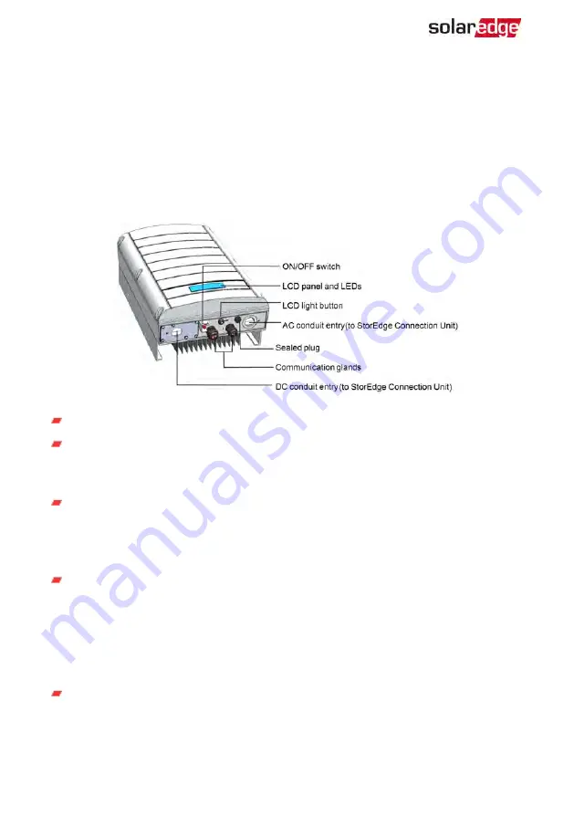
Inverter Interfaces
The following figure shows the inverter connectors and components, located at the
bottom of the inverter.
Figure 8: Inverter Interfaces
AC and DC conduit entries: Connection points of the Connection Unit.
Two communication glands, for connection of inverter communication options.
Each gland has three openings. Refer to
Setting Up Communication to the
Monitoring Platform on page 96 for more information.
LCD light button: Pressing this button lights up the LCD for 30 seconds. In addition,
you can press this button to view inverter status screens and access configuration
Configuring the Inverter Using the LCD Light Button on
ON/OFF switch: Turning this switch ON (after the power optimizers are paired with
the inverter) starts the operation of the power optimizers, enables power
production and allows the inverter to begin exporting power to the utility
grid/backed-up loads. Turning it OFF reduces the power optimizer voltage to a low
safety voltage and inhibits exportation of power. When this switch is OFF, the
inverter control circuitry remains powered up.
LCD panel: displays inverter information and configuration parameters
StorEdge Solution with Backup MAN-01-00262-1.5
32
Identifying the Inverter


