


20. RECORDING DATA - RECORD MENU -
92
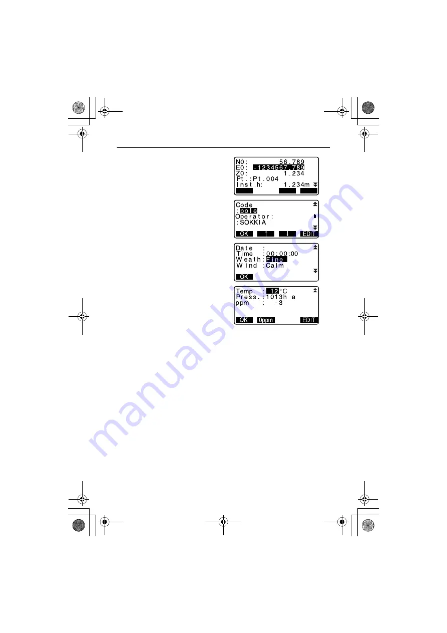
3. Press
[EDIT]
and set the following
data items.
(1) Instrument station coordinates
(2) Point number
(3) Instrument height
(4) Codes
(5) Operator
(6) Date
(7) Time
(8) Weather
(9) Wind
(10)Temperature
(11)Air pressure
(12)Atmospheric correction factor
• When inputting code, press
[
↑
] /
[
↓
]
to use the registered codes.
Align the cursor where you want
to input the registred code.
• To set the atmospheric
correction factor to 0ppm, press
[0ppm]. The temperature and air
pressure are set to the default
setting.
4. Check the input data, then press
[OK]
.
5. Press
{ESC}
to quit measurement
and restore <REC>.
$
• SET automatically increments the last input number by 1.
• Maximum point number size: 14 (alphanumeric)
• Input range of target height: -9999.999 to 9999.999 (m)
• Maximum code/operator size: 16 (alphanumeric)
• Weather selection: Fine, Cloudy, Light rain, Rain, Snow
• Wind selection: Calm, Gentle, Light, Strong, Very strong
• Temperature range: -30 to 60 (°C) (in 1°C step)/-22 to 140 (°F) (in 1°F step)
• Air pressure range: 500 to 1400 (hPa) (in 1 hPa step)/375 to 1050 (mmHg)
(in 1mmHg step)/14.8 to 41.3 (inch Hg) (in 0.1 inch Hg step)
• Atmospheric correction factor range (ppm): -499 to 499
READ
OK
EDIT
a
9
J a n / 2 8 / 2 0 0 1
a
P
a
30R.book 92
ページ
2003年12月16日 火曜日 午後5時15分
Summary of Contents for 30R Series
Page 8: ...vi 30R book vi ページ 2003年12月16日 火曜日 午後5時15分 ...
Page 172: ...29 REGULATIONS 164 CE Conformity Declaration 30R_29 FM 164 ページ 2003年12月18日 木曜日 午後5時11分 ...
Page 173: ...165 29 REGULATIONS 30R_29 FM 165 ページ 2003年12月18日 木曜日 午後5時11分 ...
Page 177: ...30R book 1 ページ 2003年12月16日 火曜日 午後5時15分 ...
Page 178: ...8th ed 13 0408 Printed in Japan 2002 SOKKIA CO LTD 30R_C3C4 FM 2 ページ 2004年8月23日 月曜日 午後5時43分 ...