SUNSYS HES L - 551697A - SOCOMEC
54
EN
8.4.2.1. Power cables connection
WARNING!
Cable glands must not be removed during the normal function of the product; use only the cable glands
provided with the C-Cab for the installation.
Make sure that all the glands are in place and that no hole remains uncovered after the installation of cables
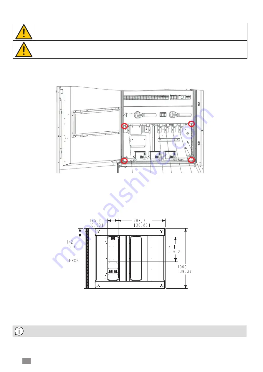
In order to access the terminals for the connection of cables, unscrew the 4 screws at the corners and remove the plastic
panel protecting the connection area in front of the terminals.
Figure 48. Screws of the plastic panel
The bottom part of the machine is provided with 4 metal plates that are used for the passage of cables. This part is located
inside the C-Cab as shown on the below figure:
In order to grant the IP55 protection of the cabinet, the cables have to be installed following the instructions in the present
manual.
3 cable glands are provided for the passage of small cables; the cable glands for power cables are not installed by default
and it is necessary to drill the plates with the required number of holes according the layout of the installation.
Note: ensure that the cabling is not under excessive stress and not pressing any sharp edge or adjacent terminal;
adjust and strap/lace in place as required.


