


NETYS RT 5 - 7 - 9 - 11 kVA - 551570A - SOCOMEC
79
EN
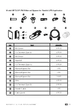
NRT3-OP-PMB
All the equipment and the UPS system must be properly connected and there must be an
acceptable AC voltage present. Please refer to the UPS User Manual for more information.
Do not remove the cover plate of the Manual Bypass’ BYPASS BREAKER
during operation.
1
Turn on the input utility breaker on the service panel.
2
Turn on the Manual Bypass’ UPS-1 OUTPUT BREAKER.
3
Turn on the Manual Bypass’ UPS-2 OUTPUT BREAKER.
4
Turn on the circuit breaker on each connected external battery pack.
5
Turn on the UPS1’s INPUT BREAKER. After that, the fans will turn on and the
UPS1 will run in bypass mode.
6
Turn on the UPS2’s INPUT BREAKER. After that, the fans will turn on and the
UPS2 will run in bypass mode.
If there is a power interruption while the UPS1 and UPS2 are both in
bypass mode, the connected loads won’t be protected.
7
Turn on the connected loads.
8
Press and hold the UPS1’s ON/ OFF button for 3 seconds and release it after
you hear one beep to turn the UPS1 on.
9
Press and hold the UPS2’s ON/ OFF button for 3 seconds and release it after
you hear one beep to turn the UPS2 on.
10 Please refer to the UPS User Manual for more information.
10.2.8. Maintenance
NRT3-OP-MBP
1
Press and hold the UPS’s ON/ OFF button for 3 seconds, release it after you hear one
beep, use the Scrolling Up or Down button to select 'Yes' and press the Enter button to
confirm your selection. The inverter will be off and the UPS will transfer to run in bypass mode.
2
Remove the screw shown in
Figure 10-14
to remove the cover plate of the
MANUAL BYPASS SWITCH.
Screw
W
AR
N
IN
G:
O
PE
N
IN
G
T
H
IS
C
O
VE
R
P
LA
TE
W
ILL
C
AU
S
E
IN
VE
R
TER
SHUT
D
O
W
N
.
O
N
LY
A
U
TH
O
R
IZ
ED
SE
R
VI
C
E
PE
R
S
O
N
N
E
L
C
AN
O
PE
N
AND
OP
ER
ATE
IT
.
MANUAL BYPASS SWITCH
TO UPS OUTPUT
L
N
TO UPS INPUT
L
N
TO UPS PARALLEL TO UPS PARALLEL
INPUT
OUTPUT
O
U
TP
U
T
SO
C
KE
T-
2
20
A
M
AX
. P
ER
O
U
TL
ET
O
U
TP
U
T
SO
C
KE
T-
1
10
A
M
AX
. P
ER
O
U
TL
ET
O
U
TP
UT
BR
EAK
ER
-2
25
0V
A
C
25
A
O
U
TP
UT
BR
EA
KE
R
-1
25
0V
AC
2
0A
(Figure 10-14)