NETYS RT 5 - 7 - 9 - 11 kVA - 551570A - SOCOMEC
44
EN
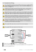
7.4. Parallel Units Wiring
You can parallel a maximum of two UPS units. To enhance parallel reliability,
please adopt the Daisy Chain method to execute parallel configuration.
Please see
Figure 7-4
.
Please ensure that each parallel UPS’s wiring is correct, and all external
output protective devices are in the ‘OFF’ position. For the location of
output protective devices, please see
Figure 7-3
.
When UPS units are paralleled, the diameter and the length of each parallel
UPS’s input cables and output cables must be equal. This ensures that the
parallel UPS units can equally share the equipment loads in bypass mode.
Before start-up of the parallel system, make sure that each UPS’s ID is
correctly set up and each unit’s major parameters are set the same. For the
major parameters’ information, please contact service personnel.
Ensure that each parallel UPS is completely turned on before starting up
the loads. To prevent the UPS from activating the overload protection
mechanism during the start-up process, please turn on the high-power
loads first and then the low-power loads.
The parallel UPS units cannot connect with common batteries.
The parallel UPS units cannot run in ECO mode.
UPS 1
UPS 4
1Ø3W
1Ø2W
Main AC
Source
Loads
AC Input
Terminal
Block
UPS Output
Terminal
Block
AC Input
Terminal
Block
UPS Output
Terminal
Block
Parallel Port
Parallel Port
Parallel Port
Parallel Port
Parallel Cable
Daisy Chain
Method
Parallel Cable
(Figure 7-4: Parallel Units Wiring Diagram)
1 Please follow steps 1 ~ 4 stated in
7.3 Single Unit Wiring
.
2 Use the provided parallel cable to connect the parallel ports on the parallel units.
3 Ground the parallel UPS unit.


