background image

MV-32/64 Multiviewer

www.snellgroup.com

Operation

Issue 1 Rev 11

Page 62

© 2014 Snell Limited

4.16.5.2

Audio Properties Tab MV-VIP3/3D (Video or Audio object)

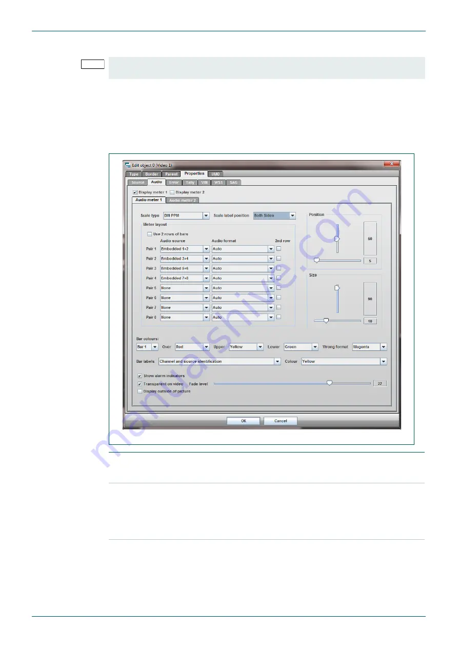
This tab only exists within the Properties tab of Video and Audio type tiles. It controls the 
audio meters that can be displayed in each window. There can be up to 4 meters per window, 
each pair of meters are controlled by separate sub-tabs within this section. 

The 

Audio meter 1

 tab is used to configure up to two meters in the left part of the tile and the 

Audio meter 2

 tab is used to configure up to two meters in the right part of the tile. The 

configuration options for both tabs is the same and so only one tab is shown here. 

Note:

This section applies to MV-VIP3 and MV-VIP-3D cards only. For MV-VIP2 Audio tab details 
see section 4.16.5.3.

Fig 51. Edit Object - Properties - Audio Tab. 

Display meter 1 and 

Display meter 2 

tick boxes 

Enables/disables each of the 2 audio meter groups.

Scale type

Sets the scale type of all the audio meter bars on display in this meter 
(including the second row if it is selected), see section 2.2.7 to see an 
example of each scale type.

Note

: The Scale Type selected for meter 1 is also used for meter 2 

when both meters are displayed.

Scale Label Position Sets the positioning of the scale labelling on either side of the meter.

Table 35.

Edit Object - Properties - Audio Tab.

Summary of Contents for MV-32

Page 1: ...snellgroup com User Manual MV 32 64 Multiviewer Enables up to 32 or 64 channels of video to be viewed on a single display device...

Page 2: ...MV 32 64 Multiviewer www snellgroup com Issue 1 Rev 11 Page 2 2014 Snell Limited...

Page 3: ...aptions and UMDs 13 2 2 3 Using bitmaps 13 2 2 4 Keeping time 13 2 2 5 Genlocking 14 2 2 6 Using GPI I O 14 2 2 7 Bargraph scales 14 3 Installation 15 3 1 Power and fuses 16 3 2 Health and safety cons...

Page 4: ...ce Properties 55 4 16 Edit Object Window 56 4 16 1 Edit Object Type Tab 56 4 16 2 Edit Object Border tab 58 4 16 3 Edit Object Parent Tab 59 4 16 4 Edit Object UMD Tab 60 4 16 5 Properties Tab 61 5 Co...

Page 5: ...107 A 2 Formatting 107 A 3 Connections 107 A 4 Transactions 108 A 5 Commands 108 A 5 1 Commands Summary 109 A 5 2 Object related commands 110 A 5 3 Source related commands 113 A 5 4 Module related com...

Page 6: ...MV 32 64 Multiviewer www snellgroup com Contents Issue 1 Rev 11 Page 6 2014 Snell Limited...

Page 7: ...ms prohibited No part of this publication may be transmitted or reproduced in any form or by any means electronic or mechanical including photocopy recording or any information storage and retrieval s...

Page 8: ...rmance of Cables and Connectors Snell products are designed to meet or exceed the requirements of the appropriate European EMC standards In order to achieve this performance in real installations it i...

Page 9: ...o outputs is 64 channels using 2 x output boards Any input may be routed to single or multiple outputs 2 1 System concept The modular architecture is designed for scalability Of the two 3U frame types...

Page 10: ...VIP1 no longer supplied Composite S video RGB YUV SD SDI DVI I Card Type MV VIP2 no longer supplied Composite S video RGB YUV SD SDI HD SDI 3 Gb s Level A 1 5 Gb s DVI I Overlay of audio and graphics...

Page 11: ...ted in a Multiviewer frame run on the same firmware version and must be compatible with that firmware version The following table gives details of the firmware that each of the card types is compatibl...

Page 12: ...cards MV VIP3D only Audio metering of Dolby E encoded on any SDI embedded audio pair Up to four Dolby encoded pairs per SDI source can be metered In total 32 mono audio channels can be metered Decodi...

Page 13: ...VITC is available from SDI sources only 2 2 2 Captions and UMDs Captions or Under Monitor Display UMD information may be generated manually from a keyboard connected to a front panel USB 2 port or aut...

Page 14: ...lack or HD tri level sync using the genlock input 2 2 6 Using GPI I O Assignable GPI I O with 16 inputs and 8 outputs for external alarm indication and tally functions 2 2 7 Bargraph scales The follow...

Page 15: ...370 mm from the front panel Maximum operating ambient temperature must not exceed 40oC Note If installing other equipment immediately above or below it is essential that the ventilation outlets are n...

Page 16: ...st if the unit is subjected to direct flames or excessive temperature of above 100 Degrees Centigrade ambient The mounting and installation of the unit must be arranged by the user to comply with all...

Page 17: ...2 Dual Multiviewer Rear Panel Connections The MV 32 dual multiviewer shown below is fully equipped with single width video rear panels Note MV VIP3 and MV VIP3D cards cannot be used with DVI inputs or...

Page 18: ...s If audio cards are installed a minimum of one video card must be fitted in slot 1 with a loop through rear panel This allows the first audio card to be fitted in slot 3 Slots 17 and 18 are reserved...

Page 19: ...S Video Y C Component video RGB YUV MV VIP1 video cards support the following standards no longer supplied Composite video PAL NTSC CVBS 1Vpp SDI SMPTE 259M DVI I digital or analog component 1920 x 1...

Page 20: ...re configured screen layouts on a chosen colored background The pair of outputs may either be set to provide two identical display configurations or they may have differing arrangements 3 4 3 Audio I...

Page 21: ...ard jumpers and Table 2 shows the jumper settings Note Only the upper port is active on the single type MV 32 MV 64 Multiviewer frame The lower port is only used for the dual MV 32 Multiviewer type fr...

Page 22: ...ignment of the connector is given in section 5 1 6 Fig 9 AES EBU digital audio input card balanced unbalanced settings Jumper Position Description 1 2 Balanced 2 3 Unbalanced Table 3 Balanced Unbalanc...

Page 23: ...ts the opening of the MV 32 MV 64 front panel and the cards cannot be inserted removed from the MV 32 MV 64 The backup power supply should be mounted above the MV 32 MV 64 2 Do Not use any other 24VDC...

Page 24: ...or details Fig 12 CN500 Connector 25 Way D Type Shell Male Pin Number Signal Pin Number Signal 1 On Off A 14 CS 2 AC OK A 15 On Off C 3 DC OK A 16 AC OK C 4 V Trim A 17 DC OK C 5 T Alarm A 18 V Trim C...

Page 25: ...t Normally Used Positive sensing The S signal should be connected to the positive terminal of the load The S and S leads should be twisted in a pair to minimize the noise pickup effect The maximum lin...

Page 26: ...hen all the scaler devices will be shut down video inside the tiles will disappear An on screen warning message will appear and persist before this occurs while the temperature is above 55 C The secon...

Page 27: ...odule has the default IP address 192 168 0 121 In the event that the multiviewer IP address is unknown a simple PC utility is available from Snell Customer Support see page 7 for contact details This...

Page 28: ...uration screen select Module then Setup Module Enter the correct IP settings and save The MV will then close the configuration window and restart with a new IP address You will need to enter this new...

Page 29: ...ssage next time the browser is to be accessed assuming that the same system is to be used Note The default IP address is 192 168 0 120 192 168 0 121 for second CPU in dual frame Depending on the syste...

Page 30: ...and selecting an available source The currently selected tile object is highlighted with a blue border Tiles can be moved and resized using conventional mouse operations For example multiple tiles may...

Page 31: ...also shown shaded in the editor workspace In the example Fig 15 the shaded area on the left is the area reserved for Audio meter 1 and the shaded area at the bottom is the area reserved for the UMD T...

Page 32: ...n the Object Folder in the Explorer view Audio and Alarm settings can be configured for each source by double clicking on its entry in the Source Folder in the Explorer view Right click context menus...

Page 33: ...o the display output and preview every time it is changed in the edit workspace Update Layout Transfer edit workspace layout to display output and preview Get Layout Transfer the current display layou...

Page 34: ...o power off power on again Rebooting the module will shut the system down and start it back up again This can take up to 70 seconds Resetting the module leaves the CPU running but resets and reloads t...

Page 35: ...appropriate fields and then press the Set button A battery on the CPU board ensures that time data is retained should the unit be powered down NTP In this mode the time is sourced from an NTP server...

Page 36: ...Loads a previously saved layout into the editor workspace Click on the Update Layout button to transfer the layout to the multiviewer display output screen Save Layout Saves current layout A name mus...

Page 37: ...round Table 13 Layout Properties Fig 23 Group Menu Select All Objects All objects in the layout will be selected and can be operated on as a group Un select All Objects Cancels group all objects comma...

Page 38: ...s the display properties of the currently selected tile object excludes source properties Paste Object Pastes the copied display properties of the currently selected tile object Paste New Object Creat...

Page 39: ...tion on the Browser CPU module firmware and scaler firmware versions Fig 25 Grid Menu Snap to Grid Tick to enable tiles to be snapped to the nearest grid position when repositioning The top left corne...

Page 40: ...es dialog covers parameters common to the whole MV rack such as IP address and GPIs It also covers initial setup of the inputs and outputs of the unit 4 11 1 Boards Tab Fig 27 Module Menu Boards Tab S...

Page 41: ...lay output aspect ratio to match the display device Genlock Lock the display output to the MV 32 MV 64 external reference Table 18 Module Menu Screen Tab Important The Resolution and Aspect Ratio shou...

Page 42: ...ming of sources These are not the names that get transferred to UMDs they are simply user names to assist with identifying sources from within the Web interface Table 19 Module Menu Sources Tab Note S...

Page 43: ...ut 1 to 8 Audio monitor output channel selection controls Select the source and source channel number to be directed to the monitor output Table 20 Module Menu Audio Monitor Outputs Tab Fig 31 Module...

Page 44: ...44 2014 Snell Limited 4 11 6 GPIs Tab GPO Alarms Sub Tab Fig 32 Module Properties GPIs Tab GPO Alarms Tab GPO Alarm Number Select GPO alarm output number 1 to 8 Alarm Source Assign alarm source to the...

Page 45: ...Volts will toggle the current state An example of a transition sensitive task is the Full Screen Toggle If the relevant window is currently at its normal size then a transition from 0 Volts to 5 Volt...

Page 46: ...gs Un check for entry of fixed network settings IP Address Enter fixed IP address if required Netmask Enter network mask if required Gateway Enter gateway address if required DNS Server 1 Enter DNS se...

Page 47: ...serial port settings can be set as required for the attached device Fig 35 Module Properties Protocols Serial Ports Tab Configure The Configure button is used to edit the serial port settings Fig 36 S...

Page 48: ...ress 64 Assigns display address 64 to source 1 video input 1 display address 65 to source 2 video input 2 etc MV 32 only TSL UMD address 96 Assigns display address 96 to source 1 video input 1 display...

Page 49: ...uter the UMDs will be updated The Controller list box at the top of the tab displays the details of any configured routers The New Edit and Delete buttons are used to set up Snell controllers that use...

Page 50: ...in the router This will allow the IP addresses of both controllers to be entered Name Enter a suitable name for the router This will be the name used in the list of controllers that can be chosen when...

Page 51: ...applicable multiviewer input select the Snell controller that controls the router that the source originates from by clicking on the controller The options available from the drop down list are the S...

Page 52: ...ital and Analog reference level adjustments above have no effect when digital audio is used with a digital scale Alarms section Here the thresholds for Audio Loss Audio Over and Antiphase alarms can b...

Page 53: ...hand section of the window and check the Enabled box to activate the alarm Enabled alarms are shown with a green circle before the descriptive text Fig 42 Source Properties Alarm Tab Select alarm Clic...

Page 54: ...he sources from list at the right that are to be copied to Multiple sources can be selected by holding down the Ctrl key while clicking on sources To execute the copying press the Copy To button Fig 4...

Page 55: ...f 30 to 3 dBfs Analogue Audio Reference Set the 0dB reference level with respect to analog meter scales It can be set within the range of 12dBu to 12dBu Note The Digital and Analog reference level adj...

Page 56: ...e from None Video Audio Text Logo and Clock Name Name of the tile can be up to 40 characters long X Y Width Height Size and position of the tile can be altered by entering figures here and any adjustm...

Page 57: ...or width respectively will be automatically adjusted to retain the ratio If None is selected the tile can be freely resized Video Aspect Ratio Video Objects only The video aspect ratio can be set so t...

Page 58: ...Width pixel width of the border Colour color of the border Visible turns the border on and off Table 31 Edit Object Border Tab Note The border will be displayed as a shaded area on the video tile in...

Page 59: ...ig 48 Edit Object Parent Tab Name For the currently selected tile select the parent object by name Position Set the anchor point of the currently selected tile relative to the parent object X Offset Y...

Page 60: ...on of UMD relative to the tile Separator Places a separator between the UMD the object s image and also between each line of text Tick the box to enable the Separator Select the color of the separator...

Page 61: ...y exists within the Properties tab of Video and Audio type tiles Fig 50 Edit Object Properties Sources Tab Source for a video tile this selects the source of the video to display in the tile For an au...

Page 62: ...right part of the tile The configuration options for both tabs is the same and so only one tab is shown here Note This section applies to MV VIP3 and MV VIP 3D cards only For MV VIP2 Audio tab details...

Page 63: ...of audio meter bars at the bottom of the tile set to 100 If the Use 2 rows of bars tick box is ticked the vertical and horizontal slider settings are used for both meters Size Sets the vertical and h...

Page 64: ...Edit object Type tab see section 4 16 1 for details Note MV VIP3D only The number of bars that actually get displayed in each meter depends on the number of channels contained in a pair When Dolby E i...

Page 65: ...W and X Position and Size Configuration Position vertical slider C1 50 and Position horizontal slider D1 5 Size vertical slider A1 90 and Size horizontal slider B1 10 Audio Meter 2 tab settings for m...

Page 66: ...he over upper and lower range applies see section 4 4 for details on setting the levels at which the colors change Over Sets the over range color for the bar selected in the Bar Colours control Upper...

Page 67: ...alarm messages When ticked all the alarms that are currently triggered or have recently been cleared will be displayed in the tile Only one alarm type gets displayed at a time it will cycle through th...

Page 68: ...software tallies operate in accordance with TSL protocol This has up to 127 display addresses each address comprising 4 tallies and a UMD The address assigned to a source depends on how the TSL Protoc...

Page 69: ...Indicator on Enables a CC indicator to be shown in the tile if the selected closed caption type is present Display service Displays the closed caption text in the tile if ticked and selects the type...

Page 70: ...as there is currently no standard for HD sources Ancillary Timecode is available on both SD and HD sources 2 The Timecode is displayed in a fixed position near the bottom center of the tile within th...

Page 71: ...pect Ratio Auto Size video image When ticked the aspect ratio of the video will automatically respond to any changes in the selected WSS or AFD information When unticked the default video size is defi...

Page 72: ...afe Area Cage If a preset safe area cage is to be shown then choose the appropriate one from this list Setup Custom Cage When ticked a custom safe area cage can be drawn using the vertical and horizon...

Page 73: ...at are of Text type Fig 59 Edit Object Properties Text Tab Text Enter up to four lines of text and set it to visible or hidden by ticking or unticking the check boxes Alignment Justify text within the...

Page 74: ...1 Rev 11 Page 74 2014 Snell Limited 4 16 5 10 Logo Properties Tab Logo object This tab only exists in tiles that are of Logo type Fig 60 Edit Object Properties Logo Tab File name Select one of the sto...

Page 75: ...ital clock type only Timezone Tick to set the clock time to GMT or within the range of GMT 1 to GMT 12 Offset hours Applies offset from 12 to 12 hours works in combination with Timezone setting if tic...

Page 76: ...used to setup a timer to run based on the time of day or controlled by GPIs The timer can be configured to count up or down depending on the requirement When controlling the timer with GPIs the timer...

Page 77: ...the period preceding the Start at time and will then count up until it reaches the Stop at time Once it reaches the Stop at time the timer will again display 00 00 00 until the Start at time Control w...

Page 78: ...e GPI will resume the timer GPI Sources the drop down lists are used to select the GPI s used to trigger the timer Up to 10 GPI timer triggers can be configured from the GPIs Tab see section 4 11 7 fo...

Page 79: ...ss Seconds Font Font Size The font to use for the digits If the size is set to auto then the digits will be sized to fit in the window up to a certain maximum font size Countdown Colour Start at a cer...

Page 80: ...ume GPI is operated the timer will start counting down from 00 00 30 and be colored white When it reaches 00 00 10 it will change to orange 10 seconds later it will reach 00 00 00 change to red and st...

Page 81: ...uipment 5 1 Interfaces Seen from the back of MV 32 MV 64 5 1 1 D sub 9 serial interface RS232 RS422 The following table gives the pin assignments for the RS 232 RS 422 D sub 9 serial interface Fig 63...

Page 82: ...Out 7 21 GPI In 9 9 GND 22 GPI In 12 10 GPI In 1 23 GPI In 15 11 GPI In 4 24 GPI Out 3 12 GPI In 7 25 GPI Out 6 13 GPI In 10 26 5V via 0 5A re settable fuse Table 47 GPI Input Output Connector Note Th...

Page 83: ...LEDs or relays The following schematic is an example of the wiring needed when an LED is to be driven by each output The numbers on the left are the GPI output numbers and pin numbers for the outputs...

Page 84: ...nels 1 to 16 for the 44 pole sub D female connector number 1 Fig 66 15 way D type Connector Pin Number Signal Pin Number Signal 1 GPI In 1 9 GPI In 8 2 GPI In 2 10 GND 3 GPI In 3 11 GPI Out 1 4 GPI In...

Page 85: ...ts depending on the card fitted may be jumper selected per channel to be either balanced or unbalanced The settings are set via jumpers on each digital audio input card See section 3 6 for jumper sett...

Page 86: ...that are essential for getting the UMD working are Putting the serial port into TSL UMD mode and setting its baud rate Ensuring that line 1 is turned on for the UMDs 1 Check that the MV 32 MV 64 match...

Page 87: ...Software X Software Y refers to the left and right tallies on the UMD e g If you select Software1 Software1 then both the left and right tallies are turned on when the TSL sets the left tally flag c...

Page 88: ...urce for Source 2 It is assumed that Source 2 is the source for the second tile Step 1 Setup the second tile to get its tally from the hardware input 1 Double click on the second tile to open the Obje...

Page 89: ...own in Fig 70 5 Press OK and upload the changes to the MV 32 MV 64 Press the red arrow update layout in the toolbar Step 3 Hardware configuration The tally that has been setup will now activate when a...

Page 90: ...PGM and PVW outputs which place a Red or Green border around the selected output source when viewed on a monitor via the multiviewer Red indicates a PGM output and Green indicates a PVW output and sou...

Page 91: ...b DE 9 connectors Fig 72 RS422 Connector as seen from the rear of the Multiviewer and Kahuna 360 Note The pin outs shown in Table 53 are the default pin outs for the Kahuna 360 The Kahuna 360 operates...

Page 92: ...ocol Type parameter to select Tally UMD Use the Available Protocols parameter to select TSL UMD Output Only and then touch the Load button Fig 73 2 To select an RS422 port on the Kahuna 360 mainframe...

Page 93: ...e button on the Engineering Config Protocols menu to activate the protocol Fig 75 5 4 3 Kahuna 360 Peripherals Setup The peripherals menu is used to configure the way the multiviewer operates with the...

Page 94: ...Multiviewer Setup Make sure the jumpers on the multiviewer CPU Card are set correctly left Card with the Ribbon Cables Links set as follows J1 Position 2 3 J13 Position 1 2 J14 Position 1 2 1 The IP...

Page 95: ...e Serial Ports tab Fig 79 5 Click on the Configure button and set the multiviewer Protocol to be TSL UMD 6 Click on the OK button to save the configuration 7 Select the Screen tab to set the output sc...

Page 96: ...are SDi rather than DVi etc 9 Click on the OK button to save the changes 10 Once you have a multiviewer on screen layout setup double click the screen to be edited The Edit Objects dialog for that sc...

Page 97: ...put Only entry in the Loaded Protocols list and touch the Unload button followed by the Load button 17 You should now have a multiviewer layout on the monitor with UMD and Red Green Box Tallies Note I...

Page 98: ...onnection section 5 5 1 See section 5 5 1 1 for MV 32 MV 64 serial link configuration See section 5 5 1 2 for cable wiring connections to the Nucleus Nebula controller See section 5 5 1 3 for Nucleus...

Page 99: ...ntroller first see the router manual for full details Nucleus2 2463 Use Workbench to configure the Nucleus2 2463 serial port Routers Port Configuration button New Serial Port button Nucleus 2450 Use W...

Page 100: ...ntroller Primary IP Address and Port Secondary IP Address and Port IP General Remote In SW P 08 Centra Controller 2330 246xPC Set as router configuration Set to the main router control module IP addre...

Page 101: ...uter tab MV Inputs Matrix No Matrix Level Router Destination Router Association Connected Tick Box MV BNC Input 1 0 As required Destinations start at 0 As required Destinations start at 0 Tick to enab...

Page 102: ...MV 32 64 Multiviewer www snellgroup com Connection to Other Equipment Issue 1 Rev 11 Page 102 2014 Snell Limited...

Page 103: ...file transfer will begin 4 When the upload is complete restart the Java applet to update the Logo file list 6 2 Multiviewer Layout Files The Multiviewer layout settings are stored in XML format on the...

Page 104: ...to a Multiviewer 1 Use a client FTP program such as FileZilla or SmartFTP to open an FTP connection to the multiviewer Default Multiviewer IP Address ftp 192 168 0 120 ftp 192 168 0 121 for second CPU...

Page 105: ...e root folder of the multiviewer The file transfer will begin 3 When the upload is complete reboot the frame to enable the updates to take effect This will take several minutes to complete depending o...

Page 106: ...sing the password smv 3 Type update scalers 4 The status of the update will be indicated on the video output Ensure that when the process is complete all scalers have been updated there are four scale...

Page 107: ...y are simply there to comply with the Hydra Open Protocol but are ignored by the MV 32 MV 64 The response to this will be the same A 3 Connections The Hydra Open Protocol has two types of connections...

Page 108: ...ands that have failed due to errors in the command sent Within this transaction response the command results are stored in the same order that they sent in the original transaction A 5 Commands Each c...

Page 109: ...below Command Description adjustumd Updates the UMD text in an object adjustborder Updates the border of an object adjustbackground Updates the background of a text object adjusttext Updates the line...

Page 110: ...rent layout remains on screen Uploading a new layout or even uploading the current layout again will overwrite the UMD with the text stored in the layout A 5 2 2 Adjust Border Adjust the border color...

Page 111: ...ground SERIAL example MODULE ID module1 OBJECT ID text1 green OBJECT MODULE COMMAND Receive COMMANDRESULT SERIAL example ERROR 0 COMMANDRESULT Table 64 Adjust Background Send Receive Description Send...

Page 112: ...ULE ID module1 OBJECT ID text1 1 OBJECT OBJECT ID text2 0 OBJECT MODULE COMMAND Receive COMMANDRESULT SERIAL example ERROR 0 COMMANDRESULT Table 66 Hide Text Send Receive Description Send COMMAND ID s...

Page 113: ...verwrite the UMD with the text stored in the layout A 5 3 2 Set Source Tally Set the tallies for a source For each source specify the source number 0 to n tally number 0 to 2 and tally state 0 or 1 Se...

Page 114: ...Get Source Tally Get the tallies for a source For each source specify the source number 0 to n and tally number 0 to 2 Tallies 0 and 1 refer to the two software tallies and return their current on off...

Page 115: ...ication running The VERSION tag with the ID attribute set to OS indicates the version of Linux running on the system Note A single source can have more than one GPI input assigned as an input tally If...

Page 116: ...OCAL ID is set back to 0 Variant 2 Set the source of the audio monitor output to an external audio input The OUTPUT ID number ranges from 1 to 4 and selects the audio monitor output pair number The EX...

Page 117: ...re set using color names The text values available are listed here A 6 1 Color Values Colors available for setting objects that can have their color attribute set are The text values used are not case...

Page 118: ...MV 32 64 Multiviewer www snellgroup com Hydra Open Protocol Issue 1 Rev 11 Page 118 2014 Snell Limited...

Page 119: ...l values given are for a 75 ohm terminated signal Minimum sync levels 200mV Maximum sync levels 350mV Maximum peak white 900mV above black MV VIP1 4 video inputs per card no longer supplied SD SDI SMP...

Page 120: ...tiples of 32 channels AES EBU in multiples of 16 pairs with SRC 32kHz 96kHz re sampled to 48kHz LTC SMPTE 12M unbalanced 0 5Vpp Signal Outputs Video Video outputs 2 x DVI I outputs analog and digital...

Page 121: ...puts 4 outputs per video Input card assignable Audio Meter Scales and Ballistics NORDIC Overall dynamic range 54dB 12 to 42dB Attack time 10mSec Decay time 1 7 Sec per 20dB decay DIN PPM Overall dynam...

Page 122: ...nd power supply fan status indicators Two versions MV 64 Single multiviewer with up to 64 video inputs MV 32 Two separate multiviewers each with up to 32 video inputs Outline Dimensions 445mm W x 550m...

Page 123: ...fitted in the slots immediately following the last populated video card slot Slots 1 and 2 are not compatible with audio cards If audio cards are installed a minimum of one video card must be fitted...

Page 124: ...422 1 CPU Buffer card next to the PSU module RS422 2 CPU Buffer card furthest from the PSU module MV 64 RS422 1 CPU Buffer card next to the PSU module RS422 2 not used 2 x USB 2 port 1 x IEC AC power...

Page 125: ...outlet socket 3 x IEC AC power socket one for each supply that can be fitted 25 way D type CN500 into which supplied d type shell MUST be fitted for DC output to be active AC power switch Mechanical 1...

Page 126: ...MV 32 64 Multiviewer www snellgroup com Technical Appendix Issue 1 Rev 11 Page 126 2014 Snell Limited...

Page 127: ...nel and remote panel indication If installed the optional MV Power external backup PSU is able to sustain operation of the unit until while the internal PSU is replaced Remove the front panel and chec...

Page 128: ...time it is launched the following message will appear It is asking for permission to install the security certificate Tick the Do not show this again box so that you do not have to acknowledge this e...

Page 129: ...ng clarity If an analog or digital LCD Plasma screen is used check that the output resolution of the MV 32 MV 64 is set to the native resolution of the panel This will avoid forcing the LCD Plasma scr...

Page 130: ...he Analog 0dB reference to 4dBu will produce a level of 22dBfs with the color changes unaltered Changing the Analog Digital reference to 20dBfs with the analog ref still at 4dBu will produce a level o...

Page 131: ...l slots 1 to 16 have been filled with cards D 1 1 2 Video Cards Video input cards are always installed working from right to left from the front of the frame Where double width rear connector modules...

Page 132: ...mitation of two Composite video signals on inputs 1 and 2 is adhered to Fig 88 Rear Module Connector Layouts RM10 RM200 RM20 RM40 RM100 Rear Module Model Code Description Rear Width MV RM10 3 x YUV RG...

Page 133: ...eo input rear module which has 4 x BNCs and a 9 pin D Type connector When using the double width rear connector modules the video loop card is always required This is because the system architecture r...

Page 134: ...The example shown in Fig 92 illustrates how the video loop card allows the video path to remain unbroken when using a dual width rear connector in slot 1 Even if the last card in the chain has a doub...

Page 135: ...tiviewer is reduced For example if the MV 32 MV 64 multiviewer were to be configured with looping inputs dual width rear modules would be required MV RM10 In this case the total video input capacity o...

Page 136: ...rame or 16 composite SDI inputs and 16 DVI I inputs per multiviewer using the dual frame assuming double rear modules are not required for other inputs MV VIP1 and MV VIP2 MV RM10 RGB YUV rear module...

Reviews: