10
1.5 Removal and Installation
1. Place the crane in rigging mode and raise the boom. This will allow access to the hose fittings
and wiring harness connections.
NOTE:
Leave the Power and FKO cable connected to allow movement of the boom during the removal
and installation process.
2. Disconnect the reeling drum cable.
3. Disconnect the swing sensor.
4. Remove the display.
5. Remove the display cable.
6. Unscrew the four bolts and remove the old computer from its mounting and place computer on
the deck.
NOTE:
Do not disconnect the power and FKO cables.
7. The new computer is smaller than the existing one. Mount the new computer using one of the
existing bolt holes. Use the new computer as a template to drill three new mounting holes.
8. Screw in the remaining 3 bolts and ensure the computer is firmly attached.
9. Lower the boom completely. Remove the existing pressure sensors.
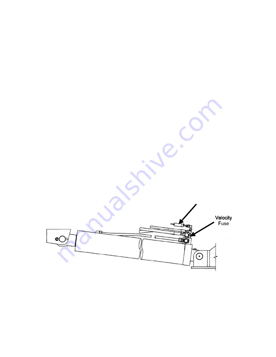
10. Install the new pressure hoses and retain the velocity fuses.
NOTE:
Install the velocity fuse In-line with base side pressure sensor. Ensure there is sufficient length
for boom travel without stretching or damaging hoses.
NOTE:
Install bleeder fittings at the cylinder. Obtain the fittings from your hose dealer.
WARNING!
Failure to ensure the velocity fuse is correctly installed may cause a dangerous uncontrolled,
downward movement of the boom in the case of hose failure.
11. Connect the new pressure hoses to the new computer.
12. Raise the boom.
13. If using the existing reeling drum, disconnect the reeling drum cable and remove. The new
computer is wired with a new cable and only needs to be attached to the reeling drum. Install
the display.
14. Install the display cable.
SkyAzúl, Equipment Solutions
www.skyazul.com
301-371-6126
Summary of Contents for Greer MG514
Page 1: ...Greer MG514 Retrofit Installation Calibration and Service Manual...
Page 2: ......
Page 4: ......
Page 88: ......
Page 89: ......


