background image

6

EN

6. Assembly

- 75 -

951-180-083-EN

Version 02

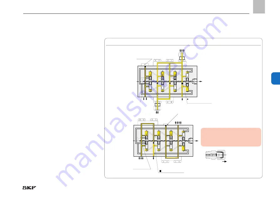
6.5.8  Consolidation of multiple outlets on the VPB (crossporting)

3

1

2 7

4

8

5

1

7

5

6

6

3

4

2

8

4

3

2 7

1

4

5

1

7

5 6

6

3

4

2

8

8

Plug screw 466-431-001

Plug  
917-006-101 removed

Plug 917-006-101  (hexagon socket WAF 3)

Plug screw 466-431-001

Plug 917-006-101  (hexagon socket WAF 3)

Plug  
917-006-101 removed

Note! 

Use only a fitting with check valve 
(VPKM-RV-S4) on the metering 
device outlet.

-See Figures 30 to 32

It is possible to subsequently connect two 
opposite outlets internally by removing a 
plug from the right outlet borehole and 
closing one of the two outlets.

Fig. 30  

VPB functional diagram of bridge designs (crossporting)

Summary of Contents for LINCOLN VP Series

Page 1: ...Version 02 951 180 083 EN 03 11 2021 EN Operating instructions according to ATEX Directive 2014 34 EU Progressive metering devices of the series VP VPK VPB EEX VP VPK VPB...

Page 2: ...directional solenoid valve 24 1254 2212 II 2G IIB T4 Gb 20 40 C II 2D IIICT135 C Db 20 40 C Metering device with proximity switch 24 1884 2288 and with 3 2 directional sole noid valve 24 1254 2219 wi...

Page 3: ...bly operation configuration maintenance repair intentional or gross negligence or accidents Use of unsuitable lubricants Improper reaction to malfunctions Unauthorized modifications to the product Use...

Page 4: ...t up 16 1 20 Cleaning 16 1 21 Special safety instructions regarding explosion protection 17 1 22 Nullification of ATEX approval 19 1 23 Operation in potentially explosive atmospheres 19 1 24 Explosion...

Page 5: ...MUR sensor 48 5 Delivery returns storage 49 5 1 Delivery 49 5 2 Return shipment 49 5 3 Storage 49 5 3 1 Corrosion protection 50 6 Assembly 51 6 1 Installation information 51 6 2 Minimum mounting dimen...

Page 6: ...t line 79 6 8 1 Assembly process 80 6 9 Assembly of the lubrication lines using quick disconnect couplings 80 6 10 Lubrication line arrangement 81 7 First start up 83 7 1 Venting a grease progressive...

Page 7: ...personal protective gear gloves Wear personal protective gear protective clothing Wear personal protective gear protective footwear Unlock the product General notes Unauthorized persons must be kept a...

Page 8: ...r example db A Sound pressure level kp kilopound kW kilowatt greater than fpsec feet per second U Voltage less than Conversion factors R Resistance plus minus Length 1 mm 0 03937 in I current intensit...

Page 9: ...angers in proper technical condition and according to the information in this manual Familiarize yourself with the functions and operation of the product The speci fied assembly and operating steps an...

Page 10: ...ices the number of cycles should be kept as low as possible by selecting high volume metering device sections A maxi mum value of 200 cycles min should not be exceeded In case of an installation on mo...

Page 11: ...potentially explosive gases and vapors whose ignition temperature is less than 125 of the maximum surface temperature Use in potentially explosive dusts whose minimum ignition temperature and glow tem...

Page 12: ...l instructions approval rules The safety data sheet of the lubricant used If applicable Project planning documents Instructions from suppliers of purchased parts Instructions for other components for...

Page 13: ...te on Pressure Equipment Directive 2014 68 EU Due to its performance characteristics the product does not reach the limit values defined in Article 4 Paragraph 1 Subpara graph a ii and is excluded fro...

Page 14: ...ity and explosion protection especially ATEX Directives 2014 34 EU and 1999 92 EC 1 14 Instruction of outside fitters Before commencing work the operator must inform outside fitters of the safety regu...

Page 15: ...nts with wet or moist hands Fuses must not be bridged Always re place defective fuses with fuses of the same type Ensure proper grounding of the product Drill required holes only on non critical non l...

Page 16: ...f necessary Lubrication lines should be filled with lu bricant prior to assembly This simplifies subsequent bleeding of the system Adhere to the specified torques Use a calibrated torque wrench when t...

Page 17: ...and work on electrical components may be performed only if it is ensured that there is no explo sive atmosphere present Repairs or modifications to explosion proof machinery may be performed only by t...

Page 18: ...onnection by hand using the locking clips provided The operator must critically examine whether operation without an empty signal results in a new hazard potential e g due to heating of bearings on th...

Page 19: ...t the operator must observe The information on explosion protection according to Directive 1999 92 EC ATEX 137 The ATEX approval 1 24 Explosion protection marking The explosion protection marking is l...

Page 20: ...a release system for hazardous activities and for those that may become dangerous in interaction with other work Performs required tests and monitoring Ensures that only original spare parts are used...

Page 21: ...ility using practical exercises The instruction includes at least Zone classification Scope and limits of the area of activ ity and responsibility for the respective group of people Safety conscious b...

Page 22: ...class 8 8 Personal injury property damage due to electric shock resulting from connection cable damage B C D E F G H Inspect power leads for damage prior to initial use and then at regular intervals...

Page 23: ...ubrication system C D G The operator must critically examine whether operation without corresponding detection options results in a new hazard potential e g due to heating of non supplied bearings on...

Page 24: ...y explosive atmosphere have all substances approved by the operator in advance Use of isolating amplifiers for example to oper ate a capacity sensor in the potentially explosive atmosphere C D G Insta...

Page 25: ...rms the basis for plan ning the centralized lubrication system The manufacturer operator of the machine should preferably make the selection with the supplier of the lubricant on the basis of the requ...

Page 26: ...check before putting back into operation that the lubricant is still suitable for use in terms of chemical and physical signs of aging We recommend performing this inspection after one week of machin...

Page 27: ...t electrical attachments do not constitute own potential sources of ignition They consequently do not fall under the scope of Directive 2014 34 EU and thus do not bear explosion protection marking To...

Page 28: ...on stroke also referred to as the compulsory stroke is determined by the position of the control bores in the metering device and the control edges on the metering piston If only the compulsory stroke...

Page 29: ...r metering device sections meter ing sections VPM and VPG cover a nominal volume per outlet and cycle of 0 1 cm3 twin section to 1 2 cm3 single section The inlet of the metering device is located at a...

Page 30: ...T twin or for one outlet S single are available In case of single sections the two opposite outlets are connected internally whereby one outlet is closed Each section is equipped with a lateral and a...

Page 31: ...metering device move sequen tially to their end position The piston move ment displaces a portion of the lubricant that is upstream of the piston to the down stream outlet A piston can start moving on...

Page 32: ...k 6a 5a 6 3a 2a 1a 4 4a 3 1 5 2 6 left front right front right back left back Piston lobe 4 is under pump pressure piston lobe 1 has dis charged to outlet 1a The connection of main line to piston lobe...

Page 33: ...al the metering device assembly The volumetric flow fed via a tube is forcibly distributed in a predetermined ratio to the outlets i e to the lubrication points or the downstream progressive metering...

Page 34: ...n a me tering device are achieved by using various metering device sections or consolidating two or more outlets For main metering device secondary meter ing device systems check valves must be used o...

Page 35: ...hat the pistons continue running reliably as defined If all pistons have moved once to the left end position as well as to the right end posi tion all connected lubrication points have been supplied o...

Page 36: ...k 6a 5a 6 3a 2a 1a 4 4a 3 1 5 2 6 left front right front right back left back Piston lobe 4 is under pump pressure piston lobe 1 has dis charged to outlet 1a The connection of main line to piston lobe...

Page 37: ...function of the neighboring piston This way the function of the block metering device can be checked by monitoring any piston by means of a cycle indicator or piston detector Attachable check valves o...

Page 38: ...ved by consolidating two or more outlets For grease systems with a main meter ing device and secondary metering device check valves must be used on the metering device outlets of the main metering dev...

Page 39: ...of the piston to the downstream outlet A piston can start moving only after the upstream piston has been moved to its end position If all pistons are in their left or right end position internal conn...

Page 40: ...apter 3 3 Information on volume data VP progressive metering device basic design Table 2 VP Basic design with terminal for equipotential bonding Type hydraulically controlled Mounting position Any Amb...

Page 41: ...00 ED at max 35 C Enclosure rating IP 67 Electrical connection 10 m cable 3x0 5 mm2 EX protection class of VP metering device with 2 2 directional solenoid valve Device labeling II 2G IIB T4 Gb 35 40...

Page 42: ...on to switching amplifier Yes Internal thread M12x1 Design PVC with 2 m cable 2x 0 34 mm2 Nominal sensing distance 4 mm Output function Contact normally closed NC Rated voltage 8 2 VDC 1k Supply volta...

Page 43: ...e data Progressive metering device VPK basic design Table 7 VPK Basic design with terminal for equipotential bonding Type hydraulically controlled Mounting position Any Ambient temperature range 25 to...

Page 44: ...max 35 C Enclosure rating IP 67 Electrical connection 10 m cable 3x0 5 mm2 EX protection class of VPK metering device with 2 2 directional solenoid valve Device labeling II 2G IIB T4 Gb 35 40 C II 2D...

Page 45: ...switching amplifier Yes Internal thread M12x1 Design PVC with 2 m cable 2x 0 34 mm2 Nominal sensing distance 4 mm Output function Contact normally closed NC Rated voltage 8 2 VDC 1k Supply voltage 7...

Page 46: ...nformation on volume data Progressive metering device VPB basic design Table 12 VPB Basic design with terminal for equipotential bonding Type hydraulically controlled Mounting position Any Ambient tem...

Page 47: ...t max 35 C Enclosure rating IP 67 Electrical connection 10 m cable 3x0 5 mm2 EX protection class of VPB metering device with 2 2 directional solenoid valve Device labeling II 2G IIB T4 Gb 35 40 C II 2...

Page 48: ...on to switching amplifier Yes Internal thread M12x1 Design PVC with 2 m cable 2x 0 34 mm2 Nominal sensing distance 4 mm Output function Contact normally closed NC Rated voltage 8 2 VDC 1k Supply volta...

Page 49: ...de of plas tic and rubber due to embrittle ment as well as components pre filled with lubricant due to aging The following conditions apply to storage The permissible storage temperature range corresp...

Page 50: ...uctua tions or high humidity take appropriate measures e g heating to prevent the formation of condensation water 5 3 1 Corrosion protection The corrosion protection should be checked and if applicabl...

Page 51: ...le position that protects it from humidity and vibration The minimum installation dimensions should be adhered to so that all other com ponents can be connected later without problems During assembly...

Page 52: ...r the ATEX progressive metering devices may be installed 6 2 Minimum mounting dimensions To ensure enough space for maintenance work and for any disassembly of the prod uct ensure that the minimum mou...

Page 53: ...um mounting dimensions 6 3 1 VP in basic design BM HM LM 24 38XX XXXX ATEX Made in Germany SKF Lubrication Systems Germany GmbH 24 38XX XXXX XYZ KW JJ II 2D c IIIC T135 CDb II 2G c IIC T4Gb 22 40 5 SW...

Page 54: ...9 9 18 204 218 3 95 VPM 10 VPG 10 10 20 224 238 4 32 The specified torques must be observed during assembly and repair Tie rod starter plate M8 2 4 Nm 0 1 Nm Nut for tie rod M8 12 Nm 1 0 Nm Inlet and...

Page 55: ...pe ZY 6 3 4 VP progressive metering device with inductive NAMUR sensor moni toring type ZS electric monitoring 26 24 38XX XXXX ATEX HM BM LM 24 38XX XXXX ATEX Made in Germany SKFLubricationSystemsGerm...

Page 56: ...17 20 35 156 6 5 57 L1 2 L2 2 max 5 10 5 72 89 6 f r VPG und VPM G1 4 SW13 SW5 B A 6 3 5 VP progressive metering device with 2 2 directional solenoid valve 6 3 6 VP progressive metering device with 3...

Page 57: ...ally with a torque of 9 Nm If necessary Tighten the inlet port screws Apply inlet port screws to the metering device inlet and tighten with the pre scribed torque Chapter 6 3 2 Tighten the outlet port...

Page 58: ...ly be subsequently consoli dated by using a VP C crossporting bar that is screwed in the upper alternative outlets Any odd number of outlets can be achieved with the help of single sections without ad...

Page 59: ...en unscrewing the self locking nuts 1 first remove the self locking nut from the tie rod The tie rod s thread must not be damaged in the process In place of the self locking nut install two nuts and p...

Page 60: ...Tie rod 2 Self locking nuts 1 Borehole for positioning the plates Guide knobs for positioning the plates Fig 17 Assembly of a three port VP progressive metering device Apply self locking nuts 1 to tie...

Page 61: ...ign 6 4 VPK port dimensions assembly holes and minimum mounting dimensions 6 4 1 VPK in basic design Minimum mounting dimensions BM Width 80 mm HM Height 50 mm LM Length L2 30 mm 24 3810 XXXX ATEX 24...

Page 62: ...44 7 1 77 VPKM 8 VPKG 8 8 16 149 4 160 9 1 96 VPKM 9 VPKG 9 9 18 165 6 177 1 2 16 VPKM 10 VPKG 10 10 20 181 8 193 3 2 35 1 This progressive metering device must be installed with check valves The spec...

Page 63: ...ve metering device with cycle switch monitoring type ZY 6 4 4 VPK progressive metering device with inductive NAMUR sensor monitoring type ZS electric monitoring Minimum mounting dimensions BM Width 13...

Page 64: ...l sole noid valve HM BM LM 51 L1 2 L2 2 max 5 8 7 6 5 54 81 5 7 5 SW5 17 15 32 153 f r VPG und VPM G1 8 SW12 6 4 17 5 19 B A Minimum mounting dimensions BM Width 100 mm HM Height 180 mm LM Length L2 6...

Page 65: ...g device inlet and tighten with the pre scribed torque Chapter 6 4 2 Tighten the outlet port screws Apply outlet port screws or SKF quick disconnect couplings to the threads of the outlet bores and ti...

Page 66: ...ine Changing the number of sections and or metering rate of individual sections while retaining the same quantity of grease sup ply changes all lubrication quantities of the outlets See Figure 23 Twin...

Page 67: ...socket screw key WAF 4 Close the outlet borehole with a plug screw The fluid of the two outlets will then flow out of the outlet near the inlet section After crossporting from 466 431 001 6 5 1 T T T...

Page 68: ...t too when unscrewing the self locking nuts 1 first remove the self locking nut from the tie rod The tie rod s thread must not be damaged in the process In place of the self locking nut install two nu...

Page 69: ...he metering device and check that it is properly sealed Inlet plate VPKM 07 Intermediate plates 7 VPKM 08 End plate 5 VPKM 09 Inlet section 3 Metering device sections 6 End section 4 Tie rod 2 Self lo...

Page 70: ...device in basic design 6 5 VPB port dimensions assembly holes and minimum mounting dimensions 6 5 1 VPB in basic design Minimum mounting dimensions BM Width 100 mm HM Height 70 mm LM Length L 40 mm BM...

Page 71: ...50 VPBM 8 VPBG 8 8 16 135 1 70 VPBM 9 VPBG 9 9 18 150 1 90 VPBM 10 VPBG 10 10 20 165 2 1 1 This progressive metering device must be installed with check valves The specified torques must be observed...

Page 72: ...ering device with inductive NAMUR sensor monitoring type ZS electric monitoring 6 5 3 VPB progressive metering device with cycle switch monitoring type ZY HM BM LM 24 3820 XXXX ATEX 25 24 3820 XXXX Mi...

Page 73: ...ional sole noid valve 6 5 7 Assembly of the VPB progressive metering device Minimum mounting dimensions BM Width 100 mm HM Height 180 mm LM Length L 60 mm HM BM LM 820 XX XX ATE X 17 15 32 153 5 60 54...

Page 74: ...rt screws to the threads of the inlet bores and tighten with the pre scribed torque Chapter 6 5 2 Tighten the outlet port screws Apply outlet port screws or SKF quick disconnect couplings to the threa...

Page 75: ...06 101 hexagon socket WAF 3 Plug screw 466 431 001 Plug 917 006 101 hexagon socket WAF 3 Plug 917 006 101 removed Note Use only a fitting with check valve VPKM RV S4 on the metering device outlet See...

Page 76: ...ridge installation position left or bridge installation position right Metering device inlet Crossporting 3 bridge with one outlet and check valve M10x1 VPBM C3 G1 8 VPBG C3 Crossporting 2 bridge with...

Page 77: ...and its equipotential bonding connection must be connected to the equi potential bonding of the main machine WARNING Explosion protection The cross section of the standard grounding cable to be suppl...

Page 78: ...metering devices may be installed 6 7 1 Connecting the inductive NAMUR sensor See Figure 34 Connect inductive NAMUR sensor ac cording to terminal diagram in Figure 34 6 7 2 Connecting directional sole...

Page 79: ...ets of the lubricant metering de vices point upwards If the system configuration requires that the lubricant metering devices be ar ranged below the main lubricant line they should not be placed at th...

Page 80: ...e lubrica tion line 1 Loosen the union nut 2 and cutting sleeve 3 from the threaded socket 4 Screw the threaded socket into the me tering device outlet 4 and tighten it Insert the lubrication line 1 i...

Page 81: ...tube See Figure 37 The SKF quick disconnect couplings are available in designs for metal pipes There is a choice available between a pipe ver sion with and without claw groove The claw groove securely...

Page 82: ...for the maximum operat ing pressure of the pump unit the permis sible temperatures and the lubricants that will be delivered The lubrication line system also needs to be protected from excessive press...

Page 83: ...to the lubri cation points Connect the hand lever grease gun or lubricating device to the metering device inlet or if present to the emergency lubricant nipple attached to the metering device Actuate...

Page 84: ...the pump pump unit until bubble free oil discharges at the outlets Retighten the lubrication line at the main metering device Repeat venting at the secondary lubrica tion lines secondary metering dev...

Page 85: ...reinstalled and functional Equipotential bonding fully present properly connected and electrically continuous No accumulated dust present 7 4 Inspections during first time start up No unusual noises v...

Page 86: ...ucts that have been de energized and depressurized Do not touch cables or electri cal components with wet or moist hands Use steam jet equipment or high pressure cleaners only in accordance with the...

Page 87: ...faces with a moist cloth 9 3 Interior cleaning The interior normally does not need to be cleaned The interior of the product must be cleaned if incorrect or contaminated lubricant is ac cidentally fil...

Page 88: ...Mechanical connection established correctly The performance characteristics for the aforementioned connections match the specifications in Technical data All components such as lubrication liness and...

Page 89: ...ings mark lines secure against outside influences Install a new metering device Notice The metering and arrangement of sections on the new metering device must be identical to the previous defective m...

Page 90: ...al control valve defective Check customer programming Establish connection of the directional control valve Send metering device to SKF to replace directional control valve No lubricant at lu bricatio...

Page 91: ...all all lines and screw unions that were removed during troubleshooting Perform start up and functional inspection System malfunction Loosen both lubrication lines on the last metering section of the...

Page 92: ...a minimum the following safety measures must be taken before any repairs Unauthorized persons must be kept away Mark and secure the work area Depressurize the product Unlock the product and prevent i...

Page 93: ...UR sensor 2 to the sen sor holder 4 and screw in gently Disconnect cable end 1 of the sensor 2 on the customer s terminal strip Apply pressure to metering device until the plunger rod 5 has extended T...

Page 94: ...d or minimized to the extent possible The disposal of prod ucts contaminated with lubricant must be performed by a recognized waste disposal company in compliance with environmental protection require...

Page 95: ...EN 14 Spare parts 14 13 95 951 180 083 EN Version 02 14 Spare parts Fig 44 VP spare parts 1 14 15 13 4 7 5 8 2 10 9 3 6 11 12 21 14 1 VP spare parts...

Page 96: ...1 006 161 471 006 351 Straight connector design EO2 for pipe 8 mm 471 008 161 471 008 351 Straight connector design EO2 for pipe 10 mm 471 010 161 471 010 351 Straight connector design EO2 for pipe 12...

Page 97: ...08 423W 441 008 511 Straight connector for pipe 10 mm tapered 1 L 410 443W Straight connector design EO2 for pipe 4 mm 1 471 004 191 471 004 311 Straight connector design EO2 for pipe 6 mm 1 471 006 1...

Page 98: ...10 mm with check valve VPM RV10 Banjo fitting for pipe 4 mm LL 445 519 041 Banjo fitting for pipe 6 mm L 445 519 061 445 531 061 Banjo fitting for pipe 6 mm LL 445 531 062 Quick disconnect coupling fo...

Page 99: ...L VPM K 4T ZY L Metering device section 5T with cycle indicator left VPG K 5T ZY L VPM K 5T ZY L Metering device section 6T with cycle indicator left VPG K 6T ZY L VPM K 6T ZY L Metering device secti...

Page 100: ...PS VPM K 3T PS Metering device section 4T VPG K 4T PS VPM K 4T PS Metering device section 5T VPG K 5T PS VPM K 5T PS Metering device section 6T VPG K 6T PS VPM K 6T PS Metering device section 1S VPG...

Page 101: ...C 11 Tie rod for 3 metering device sections length 98 0 5 mm VP 173 Tie rod for 4 metering device sections length 118 0 5 mm VP 174 Tie rod for 5 metering device sections length 138 0 5 mm VP 175 Tie...

Page 102: ...g device components VPG inch thread and VPM metric thread Item Designation VPG VPM Order No Order No 13 2 2 directional solenoid valve for grease 24 V DC 24 1254 2212 14 3 2 directional solenoid valve...

Page 103: ...EN 14 Spare parts 14 103 951 180 083 EN Version 02 14 2 VPK spare parts Fig 45 VPK spare parts exploded view 1 11 9 4 3 2 5 7 13 14 10 12 8 6...

Page 104: ...sconnect coupling for pipe 6 mm tapered 406 423W 451 006 518 VS Elbow connector according to DIN2353 for pipe 6 mm tapered 1 L 406 405W 406 405 Elbow connector according to DIN2353 for pipe 6 mm taper...

Page 105: ...1 Straight connector for pipe 10 mm tapered 1 L 410 443W Straight connector design EO2 for pipe 4 mm 1 471 004 191 471 004 311 Straight connector design EO2 for pipe 6 mm 1 471 006 192 471 006 311 Str...

Page 106: ...m with banjo fitting 504 108 VS 504 102 VS Quick disconnect coupling for pipe 4 mm tapered with banjo fitting 455 531 048 VS Quick disconnect coupling for pipe 6 mm with banjo fitting 506 108 VS 506 1...

Page 107: ...KM K 2S ZY R Metering device section 3S with cycle indicator right VPKG K 3S ZY R VPKM K 3S ZY R Metering device section 2S with cycle indicator left VPKG K 2S ZY L VPKM K 2S ZY L Metering device sect...

Page 108: ...80 0 3 mm VPKM 93 Tie rod for 4 metering device sections length 96 5 0 3 mm VPKM 94 Tie rod for 5 metering device sections length 113 5 0 3 mm VPKM 95 Tie rod for 6 metering device sections length 12...

Page 109: ...2353 for pipe 6 mm 1 L 406 403W Straight connector according to DIN2353 for pipe 6 mm tapered 1 LL 406 423 Straight connector according to DIN2353 for pipe 8 mm tapered 1 LL 408 423W 441 008 511 Strai...

Page 110: ...008 511 Straight connector for pipe 10 mm tapered 1 L 410 443W Straight quick disconnect coupling for pipe 4 mm tapered 404 040 VS 451 004 518 VS Straight quick disconnect coupling for pipe 6 mm taper...

Page 111: ...C4 Crossporting 2 bridge with one outlet port and check valve M10x1 VPBM C2 G1 8 VPBG C2 29 18 for pipe 6 mm Thread M10 1 taper G1 8 VPBM C3 VPBM C S2 Connection fitting for cross porting adjacent out...

Page 112: ...bar Image for direct screwing into a metering device outlet VPKG RV 6 R1 8 taper 3 100 1 VPKM RV S4 6 M10 1 taper 2 100 for quick disconnect coupling 2 VPKG RV4 VS 4 R1 8 taper 3 300 VPKG RV VS 6 G1...

Page 113: ...16 Appendix 16 EN 113 951 180 083 EN Version 02 16 Appendix 16 1 Declaration of Conformity proximity switch...

Page 114: ...2 Salem Neufrach dass das folgende Produkt Bezeichnung Druckfest gekapselter Einfachhubmag net Typ 01 EX14 037x yzzz EU Baumusterpr fbescheinigung FM 13 ATEX 0071X Kennzeichnung II 2G Ex db IIB H2 T4...

Page 115: ...115 951 180 083 EN Version 02 Notes...

Page 116: ...sion 02 2021 11 03 SKF Lubrication Systems Germany GmbH Walldorf Plant Heinrich Hertz Str 2 8 DE 69190 Walldorf Germany Tel 49 0 6227 33 0 Fax 49 0 6227 33 259 E mail Lubrication germany skf com www s...

Page 117: ......

Page 118: ...G IIC T6 Ga 20 70 C II 1D IIIC T90 C Da 20 70 C Metering device with proximity switch 24 1884 2288 II 2G IIB T4 Gb 35 40 C II 2D IIIC T135 C Db 35 40 C Metering device with 3 2 directional solenoid va...

Reviews: