kÉï=~ë=çÑW=
léÉê~íáåÖ=fåëíêìÅíáçåë=~åÇ=fåëí~ää~íáçå
MVKOMNS
uflp=ud=rp_=ãçÇìäÉ=~åÇ=ëÉåëçêë
båÖäáëÜ
=
Operating instructions and installation, XIOS XG USB module and sensors
XIOS XG Select
XIOS XG Supreme
Page 1: ...Éï ë çÑW léÉê íáåÖ fåëíêìÅíáçåë åÇ fåëí ää íáçå MVKOMNS uflp ud rp_ ãçÇìäÉ åÇ ëÉåëçêë båÖäáëÜ båÖäáëÜ Operating instructions and installation XIOS XG USB module and sensors XIOS XG Select XIOS XG Supreme ...
Page 2: ......
Page 3: ...used 9 2 Safety instructions 10 2 1 Qualifications of operating personnel 10 2 2 Hygiene 10 2 3 Radiation protection 10 2 4 PC system and software 10 2 5 Allocation of acquisition system to patient 10 2 6 Trouble free operation 11 2 7 Maintenance 11 2 8 Changes and extensions to the device 11 2 9 Combination with other units 11 2 10 Radiotelephones 12 2 11 Electrostatic discharge 12 3 System descr...
Page 4: ... 39 5 4 1 2 Posterior tooth exposures 40 5 4 1 3 Bite wing exposures 41 5 4 1 4 Endodontics exposures with the half angle technique 42 5 4 1 5 Measurement exposure for endodontics 43 5 4 2 Position sensor with Aimright reusable sensor holder system 44 5 4 2 1 Anterior tooth exposure 44 5 4 2 2 Posterior tooth exposures 48 5 4 2 3 Horizontal bite wing exposures 51 5 5 Select the exposure parameters...
Page 5: ... and inspection 61 6 1 Hygiene 61 6 1 1 Care cleaning agents and disinfectants 61 6 1 2 USB module and sensors 62 6 1 3 Sensor holders 63 6 2 Regular inspections 64 6 3 Replace the sensor cable 66 7 Consumables and spare parts 69 8 Electromagnetic compatibility 73 8 1 Accessories 73 8 2 Electromagnetic emission 73 8 3 Interference immunity 74 8 4 Working clearances 76 9 Disposal 77 ...
Page 6: ... XIOS XG Supreme sensors offer higher resolution compared with XIOS XG Select sensors In addition to SIDEXIS XG SIDEXIS 4 SIDEXIS XG version 2 5 6 and above the SIDEXIS plug in must be installed for XIOS XG Information on the PC software can be found in the SIDEXIS Plug in for XIOS XGOperator s Manual This operating manual should be of good help to you before use as well as serve anytime later as ...
Page 7: ... Please complete the online form if you would like a hard copy of a particular document We will then be happy to send you a printed copy free of charge Help If you continue to have difficulties despite having thoroughly studied the Operating Instructions please contact your dental depot 1 4 Other valid documents The X ray system includes other components such as PC software which are detailed in o...
Page 8: ...nsors 1 6 Indications and contraindications Indications in the areas Conservative dentistry Caries diagnosis especially of proximal lesions Endodontics Periodontology Prosthodontics Functional diagnosis and treatment of craniomandibular dysfunctions Surgical dentistry Implantology Oral and maxillofacial surgery Orthodontics Contraindications Display of cartilage structures Display of soft tissue ...
Page 9: ... the following meaning DANGER An imminent danger that could result in serious bodily injury or death WARNING A possibly dangerous situation that could result in serious bodily injury or death CAUTION A possibly dangerous situation that could result in slight bodily injury NOTICE A possibly harmful situation which could lead to damage of the product or an object in its environment IMPORTANT Applica...
Page 10: ...cable must be disinfected before each patient Refer to Hygiene 2 3 Radiation protection The valid radiation protection regulations and measures must be observed The statutory radiation protection equipment must be used Please follow the manual for your X ray tube assembly 2 4 PC system and software During the exposure the data connection and power supply must be ensured via the USB port Under Powe...
Page 11: ... can assume responsibility for the safety related features of the equipment only if maintenance and repair are carried out only by ourselves or agencies expressly authorized by us and if components affecting safe operation of the system are replaced with original spare parts upon failure We suggest that you request a certificate showing the nature and extent of the work performed from those who ca...
Page 12: ...harges from your own body through contact with a metallic unit casing a larger metallic object any other metal part grounded with the protective earth Endangered regions are indicated on the unit by the ESD warning label We recommend that all persons working with this system are made aware of the significance of the ESD warning label A training course should also be held to inform users about the ...
Page 13: ...ay lead to a charge transfer electrostatic discharge lightning arc over Integrated circuits logical circuits and microprocessors are used in order to implement a wide variety of functions in a device The circuits must be miniaturized to a very high degree in order to include as many functions as possible on these chips This leads to structure thicknesses as low as a few ten thousandths of a millim...
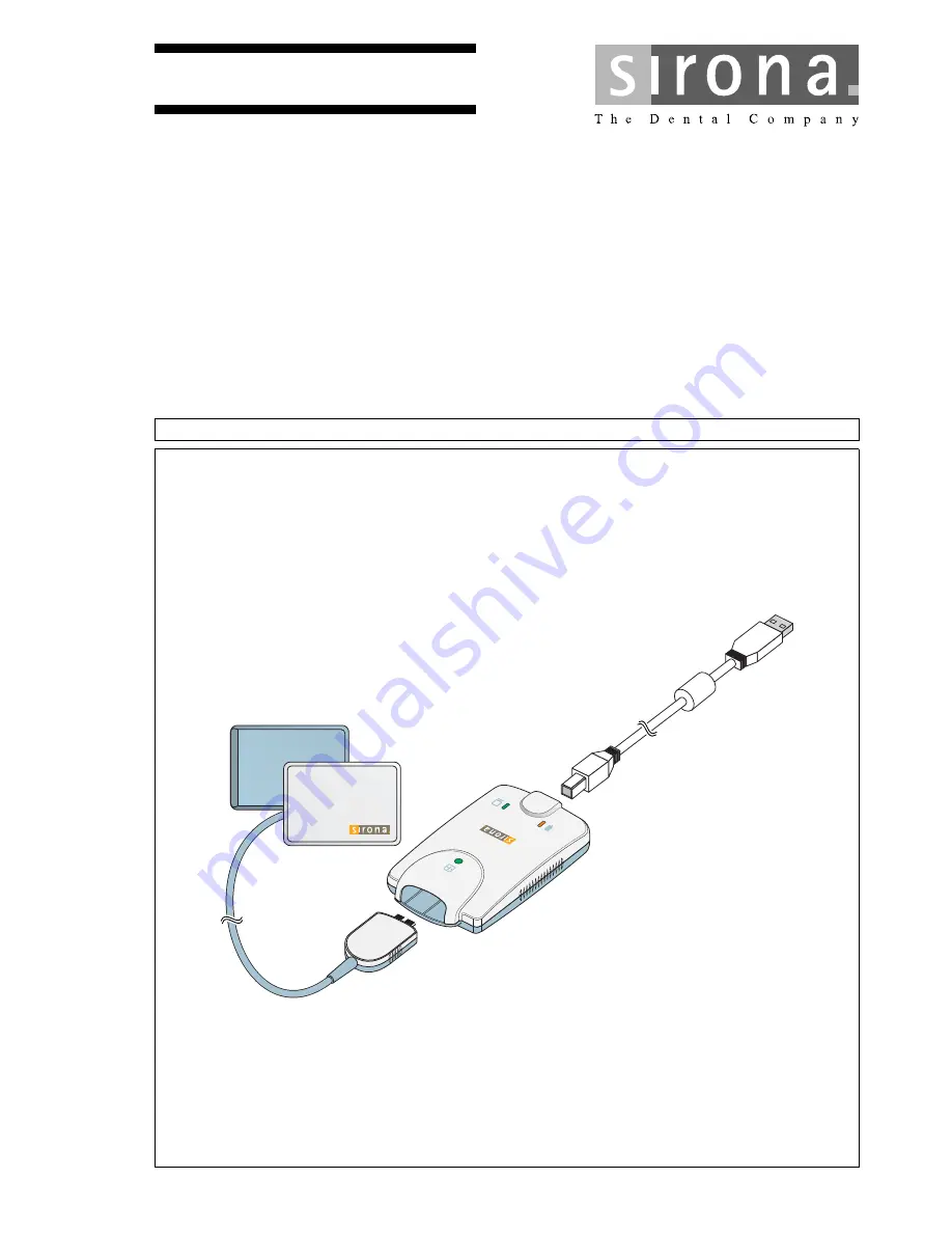
Page 14: ...10 14 D3610 201 01 08 02 09 2016 3 System description Sirona Dental Systems GmbH 3 1 System structure Operating Instructions and Installation XIOS XG USB module and sensors 3 System description 3 1 System structure ...
Page 15: ...6 C Sensor size 0 1 or 2 with cable and plug 17 D Single use sensor holder system with localizer rings guide rods sensor holder tabs 17 and hygienic protective sleeves 37 E SIDEXIS PC 20 with USB interface SIDEXIS XG SIDEXIS 4 SIDEXIS XG version 2 56 or higher SIDEXIS plug in for XIOS XG F USB hub optional 21 G Aimright reusable sensor holder system 18 with localizer ring sensor holders and hygien...
Page 16: ...he PC Image data is transferred to a PC via the USB module and USB cable Further information can be found in the Operation 33 section 3 3 USB cable A USB cable is supplied by Sirona with the delivery It meets the USB 2 0 standard and is designed especially for use on XIOS XG CAUTION Standard commercial USB cables do not offer adequate protection from electromagnetic interference Only use the speci...
Page 17: ...lters Depending on the indication you can apply the corresponding filter to the X ray image in order to amplify the relevant structures Information on the PC software can be found in the SIDEXIS Plug in for XIOS XG Operator s Manual 3 5 Sensor holder systems 3 5 1 Single use sensor holder system There are different sensor holders available depending on the type of exposure The localizer rings and ...
Page 18: ...lders available depending on the type of exposure The sensor holders are color coded The same localizer ring is used for all sensor holders The sensor holders are available for sensor sizes 1 and 2 A Localizer ring B Sensor holder for posterior tooth exposures right upper jaw left lower jaw yellow C Sensor holder for bite wing exposures red D Blue for anterior tooth exposures blue E Sensor holder ...
Page 19: ...e assembly Intraoral X ray tube assembly with multipulse technology direct current 0 14 1 4 mAs at 60 70 kV and 8 cone This information must be modified accordingly for other tube lengths or single pulse X ray tube assemblies For optimal image quality we recommend using a multipulse X ray tube assembly with a 12 cone IMPORTANT The intraoral X ray tube assembly must be installed in accordance with ...
Page 20: ... requirements Windows 7 Professional SP 1 32 and 64 bit Windows 7 Ultimate SP 1 32 und 64 bit Windows 8 1 Professional 32 bit and 64 bit Windows 10 Professional 64 bit Processor 2 GHz DualCore RAM 4 GB Free hard disk storage 5 GB for SIDEXIS 4 installation and database Removable medium CD DVD drive Graphics card 512 MB Screen suitable for diagnostics applications e g in accordance with DIN 6868 57...
Page 21: ...an active USB hub An active USB hub is only required if there is inadequate power supply via the USB port of the PC The USB hub is not included in the scope of supply It must meet the following requirements Type of protection against electric shock Protection class II USB standard 2 0 Power supply Separate power supply not bus powered Safety The USB hub must comply with standard IEC 60950 1 or be ...
Page 22: ...wer via the USB connection of the PC Supply current 250 mA Power consumption 1 25 W Maximum USB cable length 5 m Dimensions L x W x H 107 x 62 x 28 mm approx 50 g Technology CMOS APS Active Pixel Sensor Physical pixel size 15 µm image acquisition in 30 µm Line pairs 16 7 lp at 30 µm Measured resolution 16 Lp mm Theoretical resolution 16 7 Lp mm Active sensor area Size 0 sensor 18 x 24 mm Size 1 se...
Page 23: ... Collateral standard Electromagnetic compatibility Requirements and tests Quality AAMI TIR12 2004 Designing testing and labeling reusable medical devices for reprocessing in health care facilities A guide for device manufacturers CAN CSA C22 2 No 601 1 M90 Medical Electrical Equipment Part 1 General Requirements for Safety Active sensor area Size 0 sensor 18 x 24 mm Size 1 sensor 20 x 30 mm Size 2...
Page 24: ...pplied part according to IEC 60601 1 This symbol indicates that the user must read the operating manual before use CE mark in accordance with Council Directive 93 42 EEC stating the manufacturer s Notified Body This identification signifies fulfillment of the requirements of the national standards of the USA and Canada This identification signifies fulfillment of the requirements of the national s...
Page 25: ...s GmbH 3 System description Operating Instructions and Installation XIOS XG USB module and sensors 3 12 Position of the labels båÖäáëÜ 3 12 Position of the labels The following labels are attached to components of the XIOS XG USB system USB module sensors Sensor cable ...
Page 26: ...tem Definition of the patient environment in accordance with IEC 60601 1 Within the patient environment A direct contact is only permissible with devices or system parts that are approved for use in the patient CAUTION Leakage currents from the PC are transmitted to the X ray system If a PC is not sufficiently grounded there is a risk of electric shock for both the patient and the user The PC must...
Page 27: ...uctor on the PC housing To do this proceed as follows The PC is switched off and the mains cable removed 1 Put on an ESD wrist band or discharge your body by touching an equipotential bonding conductor 2 Loosen the PC housing screws and remove a PC cover Refer to the manual for the PC 3 Find a location to connect the protective ground conductor on the rear side of the metal PC housing that is read...
Page 28: ...e XIOS XG Intraoral System Make sure that the hardware and the operating system are properly installed Refer to the manuals for your PC and operating system The installation of SIDEXIS XG SIDEXIS 4 is described in the installation instructions for SIDEXIS XG SIDEXIS 4 The SIDEXIS XG SIDEXIS 4 plug in for the XIOS XG USB module must be installed in addition to SIDEXIS XG To do this proceed as follo...
Page 29: ... the device connection with USB support in the setup window 5 Follow the additional instructions 6 Restart the PC if you are required to do so The SIDEXIS plugin for XIOS XG USB system is installed 4 3 Connect USB module and hub A USB module can be connected to the USB port of a PC either directly or via an active USB hub An active USB hub is only required if there is inadequate power supply via t...
Page 30: ...ystem detects the USB module A message appears in the info area of the Windows taskbar Systray CAUTION Leakage currents from the USB hub are transmitted to the X ray system There is a risk of electric shock for both the patient and the user The USB hub should only be operated outside the patient environment up to 1 5 m around the patient Please also refer to the technical requirements for the USB ...
Page 31: ... be screwed to a wall using the drywall screws provided or any other mounting material Alternatively the holder can be glued to an even surface for example using a self adhesive Velcro strip or double sided adhesive tape Position the holder so that the USB module can be accessed easily during the treatment and the LED displays are clearly visible NOTICE There may be cables in the wall Drilling can...
Page 32: ... front socket of the USB module 3 Register a patient in SIDEXIS XG SIDEXIS 4 and establish readiness for intraoral exposures A sensor calibration file is installed automatically if you are using the XIOS XG Select or XIOS XG Supreme sensor on this PC for the first time If this does not occur and no exposure readiness is established disconnect the sensor from the USB module and plug the cable in ag...
Page 33: ...IS XG SIDEXIS 4 Detailed information can be found in the SIDEXIS XG SIDEXIS 4 operator s manual 3 Establish exposure readiness for intraoral exposures Click on the I ntraoral X ray button The Set tooth or program before exposure window opens The intraoral exposure is selected as the image type 4 Click on the tooth for which the intraoral exposure is being produced Information on the tooth displays...
Page 34: ...re readiness Operating Instructions and Installation XIOS XG USB module and sensors 5 Select the XIOS XG USB module The Exposure readiness window is displayed SIDEXIS XG SIDEXIS 4 Is ready for exposures when the green display is flashing here Exposure readiness window when using a XIOS XG Select sensor ...
Page 35: ...versal image filter is pre selected by default The orange LED on the USB module flashes the adjacent LED lights up green see Determine unit status 36 The USB module is now also ready for exposures The exposure can be released now WARNING Connecting replacing a sensor on the USB module You can connect or replace the sensor on the USB module until the radiation is released The sensor can also be exc...
Page 36: ...osure Connected Running on off on Exposure in progress Connected Not running off off on Start SIDEXIS XG SIDEXIS 4 to establish unit exposure readiness Connected Running or not running off on off Short circuit or overcurrent condition Replace the sensor cable If the problem persists replace the sensor Connected Running or not running off on flashing Undercurrent condition Replace the sensor cable ...
Page 37: ...sensor tightly and prevents the sensor from slipping out of place WARNING Sensors and sensor cables must be disinfected prior to initial use Patients may become sick due to components that have not been disinfected Remove the sensor connector from the unit Clean the sensor and the sensor cable thoroughly with disinfectant at least twice Refer to Hygiene WARNING The hygienic protective sleeves and ...
Page 38: ...older tabs may be detached and reaffixed several times during an exposure series on the same patient The sensor holder tabs must be glued to the active sensor surface A in all cases The AimRight sensor holder system is a plug in system No sensor holder tabs are required NOTICE The sensor cable is sensitive to mechanical influences The cable may become damaged or may wear out prematurely Avoid bend...
Page 39: ...into the hygienic protective sleeve see section Slide the hygienic protective sleeve over the sensor 4 Glue the sensor holder tab onto the sensor s hygienic protective sleeve Place the tab in the center of the sensor as shown in the diagram 5 Position the sensor in the patient s mouth 6 Bring the X ray tube assembly into the correct position and take an X ray exposure 7 Remove the sensor from the ...
Page 40: ... jaw Glue the sensor holder tab onto the sensor s hygienic protective sleeve Place the tab in the center on the sensor The edge of the tab must lock with the edge of the sensor as shown in the diagram 5 For the right upper jaw and left lower jaw the sensor holder tab must be placed in the mirrored position See the adjacent drawing 6 Position sensor in patient s mouth 7 Bring the X ray tube assembl...
Page 41: ...the sensor holder tab onto the sensor s hygienic protective sleeve Align the tab vertically to the sensor and place it in the center on the active sensor surface as shown in the diagram 5 For horizontal bite wing exposures the tab must be placed aligned horizontally to the sensor See the adjacent drawing 6 Position the sensor in the patient s mouth 7 Bring the X ray tube assembly into the correct ...
Page 42: ...as shown in the diagram 3 For anterior tooth exposures Glue the sensor holder tab onto the sensor s hygienic protective sleeve Align the tab to the sensor edge of the cable and place it in the center on the sensor as shown in the diagram 4 For posterior tooth exposures the tab must be aligned vertically to the sensor and placed in the center on the sensor See the adjacent drawing 5 Position sensor...
Page 43: ...e the sensor into the hygienic protective sleeve see section Slide the hygienic protective sleeve over the sensor 4 Glue the sensor holder tab onto the sensor s hygienic protective sleeve Place the tab in the center of the sensor as shown in the diagram 5 Position the sensor in the patient s mouth 6 Bring the X ray tube assembly into the correct position and take an X ray exposure 7 Remove the sen...
Page 44: ...ior tooth exposure Preparing the sensor holder For anterior tooth exposures use the blue sensor holder 1 Fasten the guide rod for the sensor holder C in the perforation B of the localizer ring A 2 Slide the sensor into the hygienic protective sleeve see Slide the hygienic protective sleeve over the sensor 3 To do this place the sensor on the palm of your hand and clip the sensor holder onto the se...
Page 45: ...ocalizer ring 2 Position the sensor in the patient s mouth 3 Use light pressure to align the sensor so that it lies parallel with the lower front teeth 4 Ask the patient to close their mouth slowly and bite down on the sensor holder 5 Slide the localizer ring onto the patient s lips 6 Align the cone of the X ray tube assembly parallel to the sensor directly on the localizer ring 7 Release an X ray...
Page 46: ... sensor must be located centrally in front of the opening in the localizer ring 2 Position the sensor centrally in the oral cavity without it touching the roof of the mouth 3 Ask the patient to close their mouth slowly and fix the sensor holder to the cutting edge Tip A cotton roll on the lower cutting edge stabilizes the sensor holder support and supports parallelism with the bite block on the se...
Page 47: ...sure parameters for the X ray tube assembly 53 and Releasing the exposure Also observe the operating instructions for the X ray tube assembly After the exposure After the exposure 1 Ask the patient to open their mouth 2 Remove the sensor from the patient s mouth 3 Remove the sensor from the hygienic protective sleeve Follow the instructions in the section Removing the hygienic protective sleeve fr...
Page 48: ...t upper jaw and left lower jaw Fasten the guide rod for the sensor holder C in the perforation B of the localizer ring A 2 For the left upper jaw and right lower jaw Fasten the guide rod for the sensor holder E in the perforation D in the localizer ring A 3 Slide the sensor into the hygienic protective sleeve see section Slide the hygienic protective sleeve over the sensor 4 Place the sensor on th...
Page 49: ...he sensor båÖäáëÜ Position the sensor 1 Look through the localizer ring to check the alignment of the sensor The sensor must be located centrally in front of the opening in the localizer ring 2 Position the sensor in the patient s mouth and align it so that it is parallel with the posterior teeth Example Positioning on the lower jaw Example Positioning on the upper jaw ...
Page 50: ... parameters for the X ray tube assembly 53 and Releasing the exposure Also observe the operating instructions for the X ray tube assembly After the exposure After the exposure 1 Ask the patient to open their mouth 2 Remove the sensor from the patient s mouth 3 Remove the sensor from the hygienic protective sleeve Follow the instructions in the section Removing the hygienic protective sleeve from t...
Page 51: ...n the guide rod for the sensor C in the perforation B of the localizer ring A 2 Slide the sensor into the hygienic protective sleeve see section Slide the hygienic protective sleeve over the sensor 3 Place the sensor on the palm of your hand and clip the sensor holder onto the sensor 4 Slide the sensor into the center of the sensor holder Position the sensor 1 Look through the localizer ring to ch...
Page 52: ... cone of the X ray tube assembly parallel to the sensor directly on the localizer ring 5 Release an X ray exposure Refer to sections Select the exposure parameters for the X ray tube assembly 53 and Releasing the exposure Also observe the operating instructions for the X ray tube assembly After the exposure After the exposure 1 Ask the patient to open their mouth 2 Remove the sensor from the patie...
Page 53: ... The lower the dosage value the higher the image noise which in turn generally leads to a poorer detail resolution Default setting for brightness and contrast Default settings for brightness and contrast can always be optimally adjusted through the image preprocessing function independent of dose 5 5 2 Recommended dose for XIOS XG sensors XIOS XG sensors have a very wide effective dose area so tha...
Page 54: ...le and 5 5 3 HELIODENT Plus exposure times 5 5 3 1 Pre programmed exposure times for XIOS XG sensors with 200 mm 8 FHA cone Exposure times by dental region XIOS XG sensors cone 8 WW 0 01 0 02 0 03 0 04 0 05 0 06 0 08 0 10 0 12 0 16 0 20 0 25 0 32 0 40 Upper jaw Lower jaw Upper jaw Lower jaw Exposure time in seconds with 60kV 0 06 0 08 0 10 0 12 0 16 70kV 0 03 0 04 0 05 0 06 0 08 Freely programmed ...
Page 55: ... Pre programmed exposure times for XIOS XG sensors with 300 mm 12 FHA cone round or square cone Exposure times XIOS XG sensors cone 12 WW Exposure times by dental region XIOS XG sensors cone 12 WW 0 03 0 04 0 05 0 06 0 08 0 10 0 12 0 16 0 20 0 25 0 32 0 40 0 50 0 64 0 80 Upper jaw Lower jaw Upper jaw Lower jaw Exposure time in seconds with 60kV 0 12 0 16 0 20 0 25 0 32 70kV 0 06 0 08 0 10 0 12 0 1...
Page 56: ... see Determine unit status 36 2 Ensure that SIDEXIS XG SIDEXIS 4 is ready for exposures The green display must be flashing in the Exposure readiness window 3 Check that the X ray tube assembly is in the correct position and take the X ray exposure 4 Remove the sensor from the hygienic protective sleeve For this follow the instructions in section Remove the hygienic protective sleeve from the senso...
Page 57: ...otective sleeve 1 Grasp the guide rod in one hand so that you can touch the side of the sensor facing away from the sensor cable with your thumb 2 Carefully push the sensor out of the part of the hygienic protective sleeve that is glued to the sensor holder tab with your thumb NOTICE The sensor cable is sensitive to mechanical influences The cable may become damaged or may wear out prematurely Do ...
Page 58: ...he hygienic protective sleeve from the sensor Operating Instructions and Installation XIOS XG USB module and sensors 3 Slide the sensor further out of the hygienic protective sleeve with your thumb 4 Hold the sensor cable firmly to prevent the sensor from falling out of the hygienic protective sleeve ...
Page 59: ...e figure 2 Carefully push the sensor out of the narrow part of the hygienic protective sleeve with two fingers 3 Slide the sensor further out of the hygienic protective sleeve 4 Hold on to the sensor and remove it from the hygienic protective sleeve NOTICE The sensor cable is sensitive to mechanical influences The cable may become damaged or may wear out prematurely Do not pull on the sensor cable...
Page 60: ...or alignment is shown on the X ray image by a small rectangle of inverted pixels Positioning the sensor Sensor alignment Inverted pixels encircled and image alignment Patient s right side Right bite wing Patient s left side Left bite wing Upper jaw Upper jaw anterior teeth Lower jaw Lower jaw anterior teeth XIOS XG Supreme XIOS XG Select XIOS XG Supreme XIOS XG Select XIOS XG Supreme XIOS XG Selec...
Page 61: ...EF number For a continuously updated list of approved agents please visit www sirona com To access the online portal for technical documentation follow the SERVICE Technical Documentation menu items in the navigation bar The portal can also be accessed directly via the following address http www sirona com manuals Click on the menu item General documents and then open the Care cleaning and disinfe...
Page 62: ...tment 134 C 273 2 F 93 C 197 F NOTICE Liquids can get into the USB module or the sensor during cleaning and disinfection The plug contacts may become wet The USB module sensor and PC can be damaged or destroyed by a short circuit Before cleaning and disinfection remove the USB plug on the PC or USB hub The system must be disconnected from the mains Also remove the sensor plug from the USB module T...
Page 63: ...le tray of the steam sterilizer ensuring sufficient distance to the walls of the steam sterilizer and the heating element 5 Sterilize in a steam sterilizer at 134 C 273 2 F for at least 3 min holding time and 2 1 bar 30 5 psi overpressure NOTICE The plastic parts of the sensor holder must not be exposed to high sterilization temperatures The plastics may melt warp or become brittle as a result of ...
Page 64: ... an appointed person must check the sensor cable thoroughly for wear and tear make sure the connector housing is fastened securely at the sensor cable Annually The image quality must be assessed by the system owner or an appointed person at regular intervals at least once a year On digital sensors the degree of postprocessing brightness or contrast adjustment that is required in the image processi...
Page 65: ...spection Operating Instructions and Installation XIOS XG USB module and sensors 6 2 Regular inspections båÖäáëÜ CAUTION The USB module must not be opened or repaired by the user All parts of the device are maintenance free In case of malfunctioning please always contact your specialized dealer ...
Page 66: ...l Sensor cable Screwdriver 2 protective screw caps 2 Elastomer strips 4 flathead screws NOTICE The electric plug contacts of the sensor are exposed during installation The sensor may be destroyed by the electrostatic discharge at the contacts Before installation discharge at a conductive grounded item e g a water faucet or a bare heating pipe NOTICE No dirt or moisture must be allowed to get into ...
Page 67: ... cable to the sensor Replace the Elastomer strip 1 Remove the existing Elastomer strip from the sensor with tweezers 2 Insert a new Elastomer strip in the slot Check that it is positioned correctly by pressing lightly with the finger The Elastomer strip must be placed exactly in the slot so that the sensor works IMPORTANT Use the new parts supplied with the cable for the assembly IMPORTANT The spa...
Page 68: ...ug for the sensor cable properly on the sensor Both parts must interlock 2 Screw the sensor cable to the sensor using the screws supplied Initially only tighten the screws until a light resistance can be felt After this tighten both screws carefully 3 Cover the screw heads with a new protective screw cap Press the cap into the plug of the sensor cable until it locks in place The cable replacement ...
Page 69: ... Yellow sensor holder tab for side tooth exposures posterior quantity 100 REF 61 76 528 Red sensor holder tab for bite wing exposures quantity 100 REF 61 76 536 Green sensor holder tab for endodontic exposures using half angle technique quantity 100 REF 61 76 544 Gray sensor holder tab for endodontics measurement exposure quantity 50 REF 61 76 551 Starter kits for single use sensor holder system S...
Page 70: ...ensor holder system Localizer ring red quantity 1 REF 65 45 599 Sensor holder for bite wing exposures red for sensor size 1 quantity 2 REF 65 45 557 Sensor holder for bite wing exposures red for sensor size 2 quantity 2 REF 65 45 565 Sensor holder for anterior tooth exposures blue for sensor size 1 quantity 2 REF 65 45 573 Sensor holder for anterior tooth exposures blue for sensor size 2 quantity ...
Page 71: ...tarter kits for Aimright reusable sensor holder system The starter kits are available for sensor sizes 1 and 2 Starter kits include the following 2 localizer rings 2 sensor holders for horizontal bite wing exposures red 2 sensor holders for posterior tooth exposures left upper jaw right lower jaw yellow 2 sensor holders for posterior tooth exposures right upper jaw left lower jaw yellow 2 sensor h...
Page 72: ...64 83 528 Sensor cable for USB module XIOS XG USB cable kit 90 cm REF 64 04 169 XIOS XG USB cable kit 180 cm REF 64 04 177 XIOS XG USB cable kit 270 cm REF 64 04 185 Radiated field limitation for HELIODENTPLUS Radiation field limitation for sensor size 0 white REF 64 00 142 Radiation field limitation for sensor size 1 black REF 62 42 007 Radiation field limitation for sensor size 2 blue REF 62 41 ...
Page 73: ...should be monitored to check and make sure that it is used properly 8 2 Electromagnetic emission The UNIT is intended for operation in the electromagnetic environment specified below The customer or user of the UNIT should make sure that it is used in such an environment System components Manufacturer Order No Serial No CDR Remote SIRONA USA Not applicable 10171017 CDR Elite Intraoral Sensor Cable...
Page 74: ...V differential mode voltage 2 kV common mode voltage 1 kV differential mode voltage 2 kV common mode voltage The quality of the line power supply should be that of a typical commercial or hospital environment Voltage dips short interruptions and variations of the power supply according to IEC 61000 4 11 5 UT for period 95 dip of UT 40 UT for 5 periods 60 dip of UT 70 UT for 25 periods 30 dip of UT...
Page 75: ...nusual performance characteristics are observed it may be necessary to take additional measures such as reorientation or repositioning of the UNIT 3 Over the frequency range 150kHz to 80 MHz field strengths should be less than 3 V m Conducted RF interference IEC 61000 4 6 3 Veff 150 kHz to 80 MHz1 3 Veff d 1 2 P Radiated RF interference IEC 61000 4 3 3 V m 80 MHz to 800 MHz1 3 V m 800 MHz to 2 5 G...
Page 76: ...mum output power of the communication device as shown below The recommended safety distance d in meters m can be determined for transmitters whose maximum power rating is not specified in the above table using the equation that belongs to the corresponding column wherein P is the maximum power rating of the transmitter in watts W according to the transmitter manufacturer Note 1 The higher frequenc...
Page 77: ...es please proceed as follows In Germany To initiate return of the electrical device please send a disposal request to enretec GmbH You have the following options here Use the Returning an electrical device button under the eom menu item on the enretec GmbH homepage www enretec de Alternatively you can also contact enretec GmbH directly enretec GmbH Kanalstraße 17 16727 Velten Tel 49 3304 3919 500 ...
Page 78: ......
Page 79: ......
Page 80: ...ëK páêçå aÉåí ä póëíÉãë dãÄe OMNS péê ÅÜÉW ÉåÖäáëÅÜ mêáåíÉÇ áå dÉêã åó aPSNMKOMNKMNKMUKMO MVKOMNS ûKJkêKW NOO SRP páêçå aÉåí ä póëíÉãë dãÄe çåí Åí áå íÜÉ rp W c Äêáâëíê É PN aJSQSOR _ÉåëÜÉáã dÉêã åó páêçå aÉåí äI fåÅK QUPR páêçå aêáîÉ Ü êäçííÉI k OUOTP rp lêÇÉê kç SQ MV TNP aPSNM ïïïKëáêçå KÅçã ...