background image


10-1


The following test features can be used when commissioning after the system is installed, and 
during periodic testing as required by code.  Refer to Chapter 12, Maintenance Procedures for 
detail on these.   
 

Refer to the page number listed in this table for information on a specific topic. 
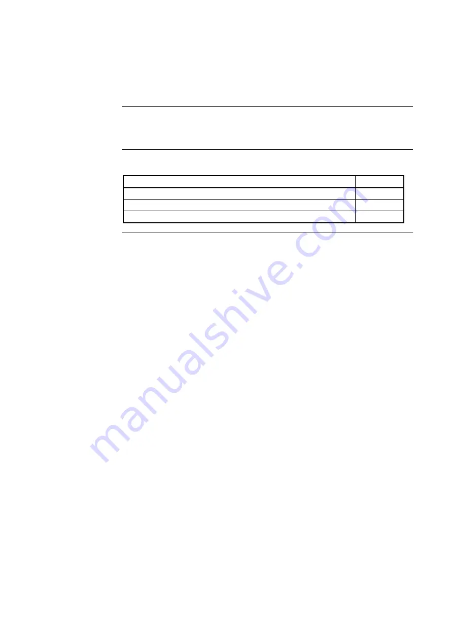
 

Topic 

See Page #

Walk Test™ 

10-2 

Walk Test™ FEATURES 

10-5 

Walk Test™ PROCEDURES 

10-8 


Chapter 10 

System Test Procedures 

Introduction 

In this Chapter 

Summary of Contents for 4100U-S1

Page 1: ...4100U Fire Alarm F I R E Operator s Manual SP1 Fire Indicator Panel Operator s Manual 4100U S1 Fire Indicator P l Operator s Manual LT0395 Iss 1 0 Operator s Manual...

Page 2: ......

Page 3: ...ation occurs the buzzer will operate until the corresponding acknowledge Ack key is pressed The panel is reset by pressing SYSTEM RESET If the alarm won t reset the point may still be activated Press...

Page 4: ...untries VESDA is a trademark of Vision Products Pty Ltd Simplex fire alarm technology is protected by the following U S Patent Numbers TrueAlarm analog smoke detection 5 155 468 5 173 683 and 5 543 77...

Page 5: ...l is dependent on custom configuration as performed by the field engineer If the configuration is not as per the recommended template then operation may differ and compliance to AS4428 0 may be invali...

Page 6: ...Isolating Silencing the EWS or External Bell 2 4 Overview 2 4 Isolating the EWS 2 4 Isolating the External Bell 2 4 Isolating the Zone 2 4 Isolating ACF Outputs 2 5 Overview 2 5 Operation 2 5 Restora...

Page 7: ...3 Chapter 6 Displaying and Modifying Detailed Point Attributes 6 1 Introduction 6 1 In this Chapter 6 1 Display Only Attributes 6 2 Select a Point 6 2 See the Attributes 6 2 Summary of Display Only At...

Page 8: ...Operation 10 4 Walk Test FEATURES 10 5 Introduction 10 5 Abort Audible and Delay on Reactivation 10 5 Active Not Active 10 5 Auto Abort on Alarm 10 5 Auto Abort on Time Out 10 5 Control List 10 5 Dela...

Page 9: ...vii In this Chapter 12 1 Weekly Tests 12 2 Procedure 12 2 Battery Test 12 2 Monthly Tests 12 3 Procedure 12 3 Annual Tests 12 4 Procedure 12 4...

Page 10: ...viii...

Page 11: ...appearance of the operator interface Refer to the page number listed in this table for information on a specific topic Topic See Page Typical Panel Layout 1 2 Basic System Description 1 3 Control Key...

Page 12: ...Overview Figure 1 1 Zone detail Emergency Operating Instructions SYSTEM IS NORMAL 08 23 43 am MON 11 DEC 00 Fire Control Figure 1 1 Typical Panel Layout Operator Interface Alphanumeric display Keypad...

Page 13: ...4100U S1 FIP Figure 1 2 Operator Interface Table 1 1 Components of the Operator Interface LED Description Refer To Zone Alarm LED This LED flashes when any Zone Alarm LED is on and the zone is not iso...

Page 14: ...ime Key Used to display the time at which an acknowledged alarm fault or isolation condition occurred Chapter 2 Entry Keypad Used to call up points for monitoring and control Chapter 5 Enable Disable...

Page 15: ...attached to the panel e g smoke detector in main lobby is in alarm Also displays system prompts and messages Important Note The degree to which you are allowed to control the system depends on the pas...

Page 16: ...pressed a fault test is performed on that zone Alarm Fault Test This key cycles between Alarm Test Fault Test and Normal for zone test modes The indicator lights when zone alarm tests are enabled the...

Page 17: ...anumeric display reports that the system is normal and shows the current time and date as shown below Note If the appearance of the operator interface is not as shown above refer to the information in...

Page 18: ...1 8...

Page 19: ...e building s EWS and external bell This chapter describes using the Operator Interface Panel keys to investigate and manage alarm conditions Refer to the page number listed in this table for informati...

Page 20: ...in the alarm condition An example is shown in Figure 2 1 Any programmed outputs including the Brigade connection operate Figure 2 1 Alphanumeric Display Showing Typical Alarm The first step in managi...

Page 21: ...the summary shown below ALARM Press FIRE ALARM ACK to review ALARMS 1 ISOLATED 0 FAULT 0 2 Press the FIRE ALARM ACK key Pressing the ACK key causes the following to occur Buzzer silences Fire Alarm in...

Page 22: ...until the warning system is de isolated When the panel has been reset leave the EWS de isolated While the alarm exists and the zone is unisolated pressing the EXT BELL ISOLATE key toggles the state o...

Page 23: ...OLATE indicator will light and the Isolate indicator above the Isolate Ack key will flash The LCD will display a message ACF ISOLATE PRESS ACK key to acknowledsge Press the Isolate Ack key to acknowle...

Page 24: ...other alarm indications the A C AUTO indicator lights to show that the 4100U S1 has taken control of the air conditioning system This operation remains in effect even after all alarms have been clear...

Page 25: ...key for a point in alarm FAULT ACK for a point in fault or ISOLATE ACK for an isolated point until the desired point is displayed 2 Press the EVENT TIME key The time and date that the point entered t...

Page 26: ...es that the system is processing the action This message is followed by a message stating No Alarms Present System Reset Complete If the individual acknowledge option is enabled on the system you may...

Page 27: ...ions exist when one or more zones have been manually isolated by an operator e g to prevent a false alarm when maintenance work e g building repairs welding is being done in an area This chapter descr...

Page 28: ...u press the FAULT ACK or ISOLATE ACK key the system displays specific data on the location of the condition In the case of Isolate it gives confirmation on the LCD that you have isolated the correct z...

Page 29: ...wledge The panel acknowledges only the fault that is currently displayed on the alphanumeric display If additional faults remain the sounder does not turn off and the FAULT indicator continues to flas...

Page 30: ...display The top line indicates the custom label of the point The bottom line contains two parts The left side of the bottom line shows the type of device The right side of the bottom line identifies t...

Page 31: ...s and points Refer to the page number listed in this table for information on a specific topic Topic See Page Alarm and Fault Test for Zones 4 2 Isolating and De isolating 4 3 Disabling and Enabling P...

Page 32: ...Alarm Test function is cancelled if the Alarm Fault Test key is pressed again or after 1 minute of no testing The fault test allows you to simulate a fault condition on a zone This allows you to test...

Page 33: ...ne A zone is isolated by pressing the appropriate Zone Isolate key on the Zone Isolate Module Zone Isolate modules are located below the Operator Interface Each Zone Isolate Module supports 8 zones 1...

Page 34: ...message indicating that the point is disabled Note To disable a point that is in alarm press the ALARM ACK key until the desired point is displayed then press the DISABLE key and the ENTER key Follow...

Page 35: ...ly turned on or off You have to acknowledge the fault by pressing the FAULT ACK key 1 Select the output point that you want to force ON Refer to Chapter 5 for information on selecting points 2 Press t...

Page 36: ......

Page 37: ...selected from the alarm fault or isolate list by repeatedly pressing the ALARM ACK key for a point in alarm FAULT ACK for a point in fault or ISOLATE ACK for an isolated point until the desired point...

Page 38: ...Analogue Pseudo Points All List Pseudo Points All Points by Address List All Network Points 1 Press the MENU key to enter the panel s menu system 2 Press the NEXT key until the alphanumeric display r...

Page 39: ...e point number If you know the full loop address then use the IDNet key The format for entering a point identifier address requires a hyphen between levels For example a module with address 12 on IDNe...

Page 40: ...lows you to select a digital P analog A or List L pseudo point Enter the number corresponding to the digital pseudo analog pseudo or list point For example pressing the P key then 2 ENTER selects the...

Page 41: ...utes of a point Refer to the page number listed in this table for information on a specific topic Topic See Page Display Only Attributes 6 2 Modifiable Point Attributes 6 4 Chapter 6 Displaying and Mo...

Page 42: ...isplays the point type which defines the specific function of the point and the card type for example Class B Multi Purpose Monitor Card Present Status Normal Alarm Fault The present status of the poi...

Page 43: ...arm Current value per cent of alarm Displays the current real time value TrueAlarm Sensors Only smoke heat VESDA or 4 20mA Peak value per cent of Alarm Displays the maximum value reported by the devic...

Page 44: ...ows the state ON or OFF of an IDNet device LED typically a smoke detector to be toggled ON or OFF This can be very useful when two devices have been set to the same point address Control Priority Chan...

Page 45: ...ueAlarm sensor Sensitivity Alarm Threshold Allows you to set the value at which the device goes into alarm The value can be any of the following Sensitivity of smoke detectors Threshold of analog ZAMs...

Page 46: ......

Page 47: ...d setting access levels for use by system operators Refer to the page number listed in this table for information on a specific topic Topic See Page Operator Access Levels 7 2 Logging In and Out of th...

Page 48: ...elects to log out The SYSTEM RESET key press has no effect upon the access level The only way to increase the operator access level in the system is to select the Change Access Level option in the Ma...

Page 49: ...u want to operate 2 Press the MENU key The alphanumeric display shows the following message 3 Press the ENTER key on the numeric keypad The following message displays 4 Press the 1 key on the Numeric...

Page 50: ...nd return the operator access level to Level 1 1 Press the MENU key The following message is displayed 2 Press the ENTER key The following message is displayed Note Logging in at access level 4 create...

Page 51: ...display shows a message similar to the one below 4 Press the C EXIT key twice to exit The display shows the system status Logging In and Out of the System Continued Log Out Procedure continued 1 Logi...

Page 52: ......

Page 53: ...tions in the system The information displayed with these lists are historical data only and will not contain any current point status Separate lists are maintained for alarms and for isolates faults T...

Page 54: ...of logged events until the desired event is shown on the display NOTE Pressing the PREVIOUS key first causes the most recent event to be displayed 5 When finished press the C EXIT key twice to escape...

Page 55: ...table for information on a specific topic Topic See Page Setting Time and Date 9 2 Displaying Software Revision 9 3 Viewing Card Status Information 9 4 Displaying Network Node Information 9 5 Lamp Tes...

Page 56: ...ween hours and minutes Use the NEXT and PREVIOUS keys to increment or decrement the value For example to change the minutes first use the and keys to move the highlight cursor under the minutes field...

Page 57: ...ion as follows SYS REV Specifies the revision of the executive software operating system of the FIP loaded in the panel CFIG FORMAT Defines the compatibility of the executive and the programmer JOB Sp...

Page 58: ...he status points for that card using the NEXT or PREVIOUS keys To view the power supply voltage and current readings perform the following procedure 1 Press the MENU key Then press the NEXT key until...

Page 59: ...mber The node number is required when selecting a network point See Selecting Points in Chapter 5 for more information on doing this 1 Press the MENU key 2 Press the NEXT and PREVIOUS keys until the p...

Page 60: ...llowing procedures to determine LED or LCD failures 1 Press the LAMP TEST push button All LEDs should illuminate LEDs should stay illuminated as long as the push button is depressed Holding the push b...

Page 61: ...cessed as M1 5 1 M1 5 2 See Chapter 5 Selecting Points for Status or Control for IDNet operations If an IDNet device will not reset you may decide to disable the point with the DISABLE key When the di...

Page 62: ...smoke detector and pressing it again will turn it off Press the NEXT key to move onto the next display Level 3 Room 74 Smoke Detector ON LINE Press the NEXT key to move onto the next display to verify...

Page 63: ...Value 75 6 of Alarm 0 1 Smoke This value is displayed as a of alarm and a of smoke obscuration per foot Press the NEXT key again to view the highest binary value that was received and stored from the...

Page 64: ......

Page 65: ...esting as required by code Refer to Chapter 12 Maintenance Procedures for detail on these Refer to the page number listed in this table for information on a specific topic Topic See Page Walk Test 10...

Page 66: ...group mode a system fault will be reported to remind you that the Walk Test is enabled Whenever a Walk Test group is aborted manually or automatically the panel will sound the abort signal three sets...

Page 67: ...disable the audible control points from the front panel one at a time The last option is to use the NO sig option controlled by the F4 key when in the Walk Test menu If this last option is selected n...

Page 68: ...ng the status of the device under test The second line of the LCD shows device status When the 4100U S1 system is placed in Walk Test mode any zone in the active Walk Test group s can be tested in any...

Page 69: ...alk Test group All groups are initially inactive at system start up Any number of groups can be enabled at any one time When a Walk Test group is enabled its associated fault pseudo point is turned ON...

Page 70: ...You cannot have the same zone in more than one Walk Test group Walk Test is a configured feature that is best programmed in the field with the 4100U Programming Unit By default Walk Test is protected...

Page 71: ...ult is detected the Walk Test signals sound continuously for four seconds The 3 key is used to enable disable Zone Coding By default Zone Coding is enabled Walk Test FEATURES Continued Fault Audible Z...

Page 72: ...this key causes an arrow to point to the active state which is displayed in capital letters 2 Key Key 2 is used to enable disable logging of Walk Test events Walk Test events are logged into the Histo...

Page 73: ...performing the following procedure 1 Press the MENU key 2 Press the NEXT key to select the Walk Test function 3 Press the ENTER key 4 Press the 1 key to turn off a Walk Test group Press NEXT then 1 t...

Page 74: ...y is shown below Press ENTER to force OFF SIGNAL CIRCUIT SIG2 3 Press the ENTER key A typical display is shown below MASTER SIGNAL POINT 2 SIG2 SIGNAL CIRCUIT OFF 4 Press the C EXIT key The display sh...

Page 75: ...current state ON or OFF but allows the system program to control it AUTO is the normal state for all control points A fault exists if any control point is taken out of the AUTO state The point to be...

Page 76: ...lay This can be viewed by pressing the FAULT ACK key and reading the alphanumeric display The point can be enabled by using the ENABLE key If the ENABLE key is passcode protected perform Log In Proced...

Page 77: ...UMERIC DISPLAY PRESS THE DISABLE OR AN FIRE ALARM ACK KEY FAILURE TO ABORT THE ENABLE WILL CAUSE AN ALARM CONDITION If the enable process is successful the following message is shown on the alphanumer...

Page 78: ......

Page 79: ...tions and how to print a report Refer to the page number listed in this table for information on a specific topic Topic See Page Setting Printer Options 11 2 Printing a Report 11 3 Chapter 11 Printing...

Page 80: ...ntil the prompt reads Printer Options 3 Press ENTER 4 Press the NEXT and PREVIOUS keys to select either of the following Select Report Printer This allows you to select which printer is to be used if...

Page 81: ...rm Shows the current value for the sensor Value is shown as a percentage of 100 percent alarm For example if the value shown is 9 it means that the sensor is currently at 9 of the value required to tr...

Page 82: ...11 4...

Page 83: ...ion on a specific topic Topic See Page Weekly Tests 12 2 Monthly Tests 12 3 Annual Tests 12 4 WARNING It is very important that adequate precautions are taken when doing any testing on the fire alarm...

Page 84: ...solate key to activate the fault test for that zone c On completion of the tests ensure that all switches are in the correct operating position and that the system has been returned to its normal stat...

Page 85: ...itions on all alarm zones to ensure that fault indicators both aural and visual where applicable are operating correctly from each alarm zone facility f Check that all control and indicating equipment...

Page 86: ...nts g Check the power supply battery supervision Disconnect the battery and check that a battery depleted missing fault occurs With the battery connected measure the voltage with a calibrated voltmete...

Reviews: