


TO measuringInput
Note
Before you insert a measuring input, the hardware must have been configured – and a TO axis
(position or synchronous axis) or a TO external encoder, to which the measuring input is
assigned, has to be created.
This is how you enter a measuring input
1. In the project navigator, highlight the folder MEASURING INPUTS under the relevant axis
or external encoder.
2. Select Insert > Technology Objects > Measuring Input, or double-click Insert Measuring
Input in the project navigator at the axis or external encoder entry in the MEASURING INPUTS
folder. The Insert Measuring Input window appears.
3. Enter a name for the measuring input.
4. Confirm with OK. In the working area, the window for the configuration is displayed and the
measuring input created is shown in the project navigator.
In the Configuration window, define the configuration data values for the measuring input.
1. Double-clicking in the project navigator below the measuring input on the Configuration
element displays the window in the working area.
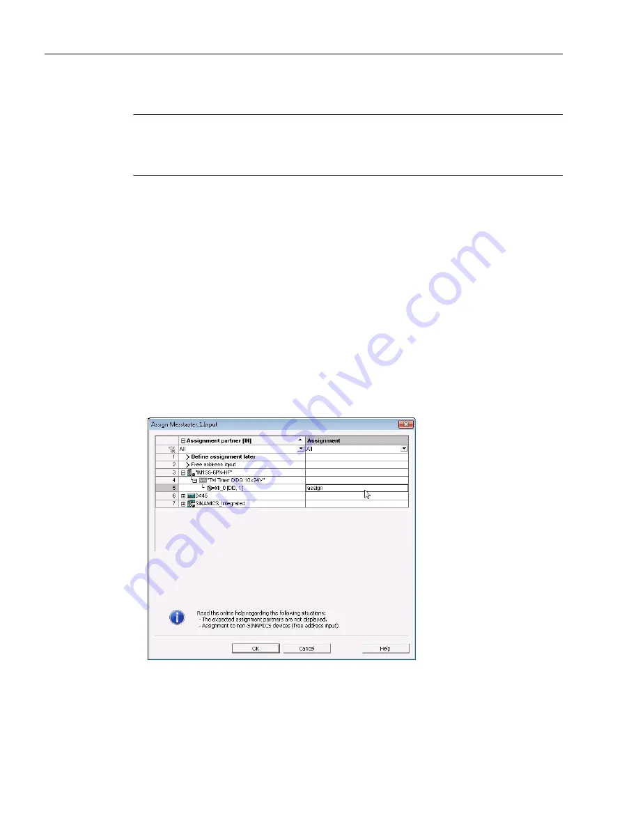
2. Assign the assignment partner MI _0 of the technology module to the input.
Figure 3-12 Assignment of measuring input input to TO measuringInput
3. Confirm with OK.
Configuring
3.2 SIMOTION SCOUT
Technology Modules TM Timer DIDQ for SIMOTION SCOUT and SIMOTION SCOUT TIA
36
Commissioning Manual, 01/2015


