3.19 High Density Unit Installation
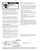
Hazardous voltage.
Will cause death or serious personal
injury.
Energized vertical bus may be partially
exposed through the access holes in the
barrier when the unit is not fully inserted.
Use extreme caution when performing
any wiring or maintenance with the unit
withdrawn.
3.19.1 Coil Removal
1. For easy coil replacement, remove the unit from the struc-
ture.
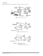
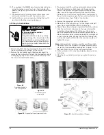
2. Loosen screw .A. which secures the cover.
3. Rotate the cover as shown in Figure 53 around the pivot
point.
4. Disconnect wiring to coil.
5. Remove coil through top of unit.
3.19.2 Terminal Block Swing Plate
1. To wire the unit, rotate the terminal block swing plate as
shown in Figure 54.
2. Route the wires from the vertical wireway into the unit
behind the right unit side angle.
3.19.3 Arc Cover Access Slots
Withdraw the unit for access to the arc cover screws through
the slots in the unit bottom plate as shown in Figure 56.
3.19.4 Hinge Installation
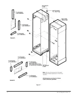
1. Remove the existing hinge (if present) in the 6. space.
2. Install the unit support bracket per 89-H2B installation man-
ual unit only.
3. Locate and install the new hinge with the two mounting
screws.
4. Install the door using two new hinge pins supplied with the
unit.
3.19.5 Unit Access For Maintenance
1. Remove the unit from the structure.
2. Loosen screw .B. shown in Figure 56.
3. Lift the handle bracket and pull forward to disengage.
4. Rotate the left side of the unit open as shown in Figure 56.
5. When closing the unit, the handle must be in the OFF posi-
tion.
Siemens Energy & Automation, Inc.
27
Figure 53
Screw “A”
Figure 54
Figure 55
Figure 56
Handle Bracket
Screw “B”

