background image

17. Verify that all ground connections have been properly 
      made. The sections of the motor control center which 
      were shipped separately must be connected in such a way 
      to assure a continuous grounding path.
18. Install covers, install units, close and secure doors, make 
      certain that no wires are pinched and that all enclosure 
      parts are properly aligned and secured.
19. Make sure the door interlocks on all disconnect operators 
      are properly adjusted and secured. If adjustment is 
      required, use the procedure explained in the Maintenance  
      section of this instruction manual.
20. Disconnect any safety grounds which have been connected 
      to the power bus.
21. Check all connections for mechanical and electrical tight-
      ness.

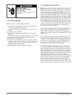
4.2 Energizing Equipment

Hazardous Voltage.
Failure to check this equipment 
prior to energization can cause 
death or serious personal injury.

All pre-energized checks outlined in 
this instruction manual must be per-
formed before the equipment is 
energized by Qualified Personnel 
only.

1. In order to minimize risk of injury or damage, or both, there
    should be no load on the motor control center when it is
    energized. Turn off all of the downstream leads, including
    those such as distribution equipment and other devices
    which are remote from the motor control center.
2. The equipment should be energized in sequence by starting
    at the source end of the system and working towards the
    load end. In other words, energize the main devices, then
    the feeder devices, and then the branch-circuit devices.
    With barriers (if applicable) in place, and unit doors closed

    and latched, turn the devices on with a firm positive  
    motion. Protective devices that are not quick-acting should  
    not be “teased” into the closed position.
3. After all disconnect devices have been closed, loads such as
    lighting circuits, starters, contactors, heaters, and motors,    
    may be turned on to verify that the system operates as  
    intended.

4.3 Permissible Loading of Motor Control Centers

1. For motor control centers without main overcurrent protec- 
    tive devices, the total continuous load current through the 
    horizontal bus should not exceed the current rating of the  
    motor control center.
2. For motor control centers with a single main overcurrent  
    protective device, the total continuous load current on the 
    protective device should not exceed 80 percent of its 
    ampere rating unless the device is rated to carry 100 per-
    cent of its ampere rating, in an enclosure.
3. For motor control centers with multiple main overcurrent
    protective devices, the total continuous current through the
    horizontal bus should not exceed the current rating of the
    motor control center. The total continuous load current on
    each overcurrent protective device should not exceed 80
    percent of its ampere rating unless the device is rated to
    carry 100 percent of its ampere rating, in an enclosure.
4. For branch-circuit overcurrent protective devices in a motor
    control center, the total continuous load current on the pro- 
    tective device should not exceed 80 percent of its ampere
    rating unless the device is rated to carry 100 percent of its
    ampere rating, in an enclosure.
5. Unless a current limiting means is used in a series combina- 
    tion, the maximum short-circuit current rating of the entire
    motor control center is the smallest of the following:
    a. the rating of the bus structure, or
    b. the lowest rating of the motor control units, or
    c. the lowest rating of the feeder units.
This motor control center rating is clearly indicated on the
lead sheet located in the information packet.

Siemens Energy & Automation, Inc.

30

Summary of Contents for TIASTAR

Page 1: ...TIASTAR Motor Control Center Instruction Guide SFIS 70060 0509 May 2009 ...

Page 2: ...sses or face shields flash clothing etc in accordance with established safety practices c is trained in rendering first aid SIGNAL WORDS The signal words DANGER WARNING and CAUTION used in this manual indicate the degree of hazard that may be encountered by the user These words are defined as DANGER For the purpose of this manual and product labels DANGER indicates an imminently haardous situation...

Page 3: ...Periodic Cleaning 33 5 4 Stab Fingers And Vertical Bus 33 5 5 Recommended Tightening Torques 33 5 6 Disconnect Operating Handle Adjustment 34 5 7 Adjustment Notes 35 5 8 Maintenance After A Fault Has Occurred 35 5 9 Disconnecting Means 35 5 10 Terminals And Internal Conductors 36 5 11 Adjustment Of SentronTM Type ETI Instantaneous Trip Motor Circuit Interrupter 1A 125A 37 5 12 Field Testing Of The...

Page 4: ...s barriersides of motor control centers 9 Horizontal ground bus 15 Unit stab holes 3 Bottom wireway 10 Divider side sheet assembly 16 Unit support assembly 4 Front bottom base channel between adjoining sections 5 Channel sills 11 Horizontal bus support 6 Top wireway 12 Standard vertical bus brace General Information 1 1 Parts Illustrations Standard Bus Siemens Energy Automation Inc 4 ...

Page 5: ...wireway 6 and formed cover plate 18 Vertical wireway 22 Bottom end cover plate 19 Removable door hinge 23 Top horizontal wireway and door wireway 12 high 20 Vertical wireway door 24 Top plates 25 Lifting angle Siemens Energy Automation Inc 5 1 1 Parts Illustrations Optional Bus ...

Page 6: ...dle the motor control center with care to avoid dam age to components and to the frame or its finish 2 Handle the motor control center in an upright position only Motor control centers are normally front heavy and frequently top heavy Balance the load carefully and steady the motor control center as necessary while mov ing Some motor control center interiors may contain heavy equipment such as tra...

Page 7: ...s 2 Place protective material between the MCC and forklift to prevent bending and scratching 3 Securely strap the MCC to the forklift to prevent shifting or tipping 4 Excessive speeds and sudden starts stops and turns must be avoided when handling the MCC 5 Lift the MCC only high enough to clear obstructions on the floor 6 Take care to avoid collisions with structures other equipment or personnel ...

Page 8: ...h is not installed and energized immediately should be stored in a clean dry space where a uniform temperature prevents condensation Preferably it should be stored in a heated building with ade quate air circulation and protected from dirt and water Motor control centers and units should be stored where they are not subject to mechanical damage If the motor control center is to be stored for any l...

Page 9: ...te mains If cables cannot be directly routed to terminals provide adequate space for clamping the cables Torque incoming lines to main lugs only at 85 ft lbs Torque all incoming connections to main circuit breakers and fusible disconnects as per the breaker or disconnect manufacturer s recommendations The torque requirements are found on a label located on the disconnecting device Outgoing Power a...

Page 10: ...ds Unless the motor control center has been designed for unusual service conditions it should not be located where it will be exposed to ambient temperatures above 40 C 104 F corrosive or explosive fumes dust vapors dripping or standing water abnormal vibration shock or tilting or other unusual operating condi tions The motor control center should be installed in a clean dry heated place with good...

Page 11: ...to holes in masonry or concrete are not recom mended for anchoring inserts and should never be used The bolt size must be 1 2 Grouting the sill channels is another method of fastening This method requires the foundation to be grooved as shown to accept the sill channels See Figure 7 for details Welding the steel base or sill channels to a steel floor plate is an alternate mounting method See Figur...

Page 12: ... that the operating personnel s working base is at the same level as the MCC base 3 5 Top and Bottom Covers Top covers are provided on all motor control centers as an inte gral part of the enclosure Bottom covers are supplied on cer tain types of construction such as NEMA 12 These covers should be removed only for the purpose of piercing holes for conduit or wire entry and must be immediately repl...

Page 13: ...Bolt structures together at six points see Figure 11 If access to the rear of the structures is restricted the rear center bolt may be omitted Note When aligning different depths of structures i e 15 front only or 20 deep front only align the fronts of the structures and bolt together using front three bolts 5 Assemble the bus bar links to join the horizontal power bus and neutral bus if supplied ...

Page 14: ...Figure 11 Siemens Energy Automation Inc 14 ...

Page 15: ...t installation details refer to instructions supplied with splice kits Figure 12 1200A 1600A L1 Connection Figure 14 600A 800A Main Bus Connection All Neutral Bus Connections 600A Horizontal Ground Bus Connection Siemens Energy Automation Inc 15 ...

Page 16: ...cement of the motor control cen ter The incoming source cables may be connected at this time however the power source disconnecting means must remain open and locked out until all wiring is completed and the entire system has been checked out Care must be exercised to make sure that the lugs which have been provided are suitable for use with the type of cables being installed in the motor control ...

Page 17: ...Siemens Energy Automation Inc 17 Figure 15 ...

Page 18: ...600MCM CU AL 17 16 24 12 600A 85 100K Top Qty 2 2 600MCM CU AL 18 20 30 18 600A 42K Bottom Qty 2 4 350MCM CU AL 19 13 18 12 600A 65K Bottom Qty 2 4 350MCM CU AL 19 13 24 18 800A 42K 65K Top Qty 2 2 600MCM CU AL 17 16 24 12 800A 85K 100K Top Qty 2 2 600MCM CU AL 18 20 30 18 800A 42K 65K Bottom Qty 2 2 600MCM CU AL 20 18 30 24 1200A 42K 100K Top Qty 3 2 600MCM CU AL 18 20 30 18 1200A 42K 65K Bottom ...

Page 19: ...Siemens Energy Automation Inc 19 3 12 Main Lugs Figure 16 Figure 17 Figure 18 Figure 19 Figure 20 Figure 21 Figure 22 ...

Page 20: ...600A 600Ad Bottom Qty 2 3 0 500MCM CU 28 15 42 36 800A 800A Top Qty 3 250 500MCM CU AL 25 15 48 36 800A 800A s Bottom Qty 3 250 500MCM CU AL 29 22 54 48 1200A 1200A Top Qty 4 250 500MCM CU AL 25 16 48 36 1200A 1200A s Bottom Qty 4 250 500MCM CU AL 29 22 54 48 1600A 1600A Top Qty 4 300 600MCM CU AL 30 42 90 72 1600A 1600A Bottom Qty 4 300 600MCM CU AL 31 26 90 72 2000A 2000A Top Qty 6 300 600MCM CU...

Page 21: ...n Circuit Breakers Thermal magnetic molded type breakers are used for mains in the MCC Siemens Energy Automation Inc 21 Figure 23 Figure 24 Figure 25 Figure 26 Figure 27 Figure 28 Figure 29 Figure 30 Figure 31 ...

Page 22: ... Top Qty 1 14 1 0 MCM CU 33 13 30 18 100A 100A Bottom Qty 1 14 1 0 MCM CU 38 7 30 24 200A 200A Top Qty 1 6 350MCM CU 34 16 42 30 200A 200A Bottom Qty 1 6 350MCM CU 39 10 48 42 400A 400A Top Qty 2 3 0 500MCM CU 35 14 48 36 400A 400A Bottom Qty 2 3 0 500MCM CU 40 14 60 54 600A 600A Top Qty 2 3 0 500MCM CU 35 14 48 36 600A 600A Bottom Qty 2 3 0 500MCM CU 40 14 60 54 800A 800A Top Qty 3 250 500MCM CU ...

Page 23: ...nas brand switch and class R fuse clips 400 to 600A Siemens molded case switch and class R fuse holder 800 to1200A Siemens molded case switch and class L fuse holder Siemens Energy Automation Inc 23 Figure 32 Figure 33 Figure 34 Figure 35 Figure 36 Figure 37 Figure 38 Figure 39 Figure 40 Figure 41 ...

Page 24: ...able regional codes or regulations 3 15 1 NEMA Type A Wiring Motor control centers with NEMA Type A wiring do not include terminal blocks All field wiring both power and control should be connected directly to the individual components 3 15 2 NEMA Type B Wiring Motor Control Centers with NEMA type B wiring include termi nal blocks for control circuit connections NEMA Type B user field load wiring ...

Page 25: ... The interlocking mechanism will not permit removing or inserting the unit with the handle in the ON position 2 Unscrew the multi turn latch on bottom plate of the unit Rotate the latch until it disengages from the separator angle Note High density 6 units do not utilize a multi turn latch 3 Open vertical wireway door 4 Move the unit to the test position by opening the racking lever Fig 44 on the ...

Page 26: ...support assembly with the two screws provided One screw fastens the right hand shelf bracket to the vertical bus support angle The second screw fastens the separator angle to the left side of the structure 4 Remove the appropriate unit stab hole covers 5 Mount the unit door by placing it on the hinges while half open Open completely and insert the hinge pins 6 Plug In Move the unit operator handle...

Page 27: ...the vertical wireway into the unit behind the right unit side angle 3 19 3 Arc Cover Access Slots Withdraw the unit for access to the arc cover screws through the slots in the unit bottom plate as shown in Figure 56 3 19 4 Hinge Installation 1 Remove the existing hinge if present in the 6 space 2 Install the unit support bracket per 89 H2B installation man ual unit only 3 Locate and install the ne...

Page 28: ... up the following procedure may be observed to help dry the motor control center Energize several individual control units If individual readings are above one megohm energize addi tional units After the equipment has been in operation for 48 hours the readings should be in the 5 20 megaohm range If at any time megger readings are below 5 megaohm one meg ohm during start up consult your local Siem...

Page 29: ...l interlocks for proper contact operation Check all mechanical interlocks for proper freedom and operation 7 Check all timers for proper interval setting and contact oper ation 8 Check overload relay trip setting or heater size and verify that they are adjusted per the instructions given for the overload relay in this instruction manual Explosive hazard Installation of fuses of insufficient interr...

Page 30: ...not be teased into the closed position 3 After all disconnect devices have been closed loads such as lighting circuits starters contactors heaters and motors may be turned on to verify that the system operates as intended 4 3 Permissible Loading of Motor Control Centers 1 For motor control centers without main overcurrent protec tive devices the total continuous load current through the horizontal...

Page 31: ... De energize motor control center Adding to a Blank Unit Space page 25 Open blank door Remove hinge pins with door open Close door halfway and remove door If necessary install unit support assembly and blank covers or doors Insert shelf brackets at a slight angle into vertical bus support angle and snap into place Secure brackets by fastening the right hand bracket to bus support angle and the sep...

Page 32: ...tails read the succeeding pages General Inspection of the MCC Periodic Cleaning Tightening Torques Stab Fingers and Vertical Bus Circuit Breaker Disconnect Operator Mechanical Interlocks A specific checklist of routine preventive maintenance require ments is recommended for each item of equipment as well as a log book to record the maintenance history 5 2 General Inspection of the MCC 1 Carefully ...

Page 33: ...ith a dry cloth or soft brush Use care to avoid damag ing delicate parts Liquid cleaners including spray cleaners are not recommended due to the possibility of residues Compressed air is not recommended for cleaning because it will only distribute contaminants on other surfaces and may dam age delicate parts The inside bottom of the motor control cen ter should also be cleaned including removal of...

Page 34: ... operating handle adjustments with the unit removed from the motor control center or in the test position 2 The adjustable link rod can adjust to increase or decrease its overall length by rotating the sleeve By rotating the sleeve clockwise the length is increased and by rotating it counter clockwise the length is decreased A hex nut is provided as part of the adjustable link rod and is tightened...

Page 35: ...n adversely effected 9 In the case of both the circuit breaker and disconnect switch the adjustment should be such they turn on with the knob no closer the 1 8 away from the escutcheon Note Always use two wrenches when loosening adjusting or tightening the adjustable link rod One wrench adjusts the hex sleeve while the second wrench holds the hex nut A provision is made for Qualified Persons to de...

Page 36: ...erform the Pre Energization checks procedures detailed on Page 29 herein before restoring the equipment to service 5 11 Adjustment of SentronTM Type ETI Instantaneous Trip Motor Circuit Interrupter 1A 125A Hazardous voltage Will cause death or serious personal injury Disconnect and lock out all power and control voltage sources supplying the motor circuit interrupter before adjusting trip setting ...

Page 37: ...s or less may be selected from the 60 C or 75 C column Select wire from the 75 C column when the motor current is greater than 100 amperes When conditions dictate the use of cables larger than these the relay tripping time may be affected Another condition which may affect tripping is a long acceleration time such as that caused by a motor driving a high inertia load If either of these conditions ...

Page 38: ...es Door hinges not properly adjusted Add or subtract shims as necessary Contactor will not close Control circuit or power fuse blown Inspect fuses replace if blown Reset circuit breaker or circuit breaker tripped Incoming power line not energized Close feeder circuit breakers or tie switch Magnet coil defective Check magnet operation replace coil as necessary Interposing relay defective Check and ...

Page 39: ...oltage Line voltage should be maintained between 10 of motor nameplate voltage Overload relay trips during Motor being overloaded Reduce load or correct conditions causing motor operation overload Overload relay not adjusted to motor Adjust relay setting in accordance with capabilities or sized properly instructions for the overload relay Adjustment should correspond to thermal rating of the motor...

Page 40: ...y damaged because of Motor power fuses may be damaged dropped improper handling or roughly handled Replace with fuse of same type rating and voltage Blowing of primary control Shorted primary wiring in control Replace or repair transformer transformer fuses transformer Fuse may be open due to rough Replace with fuse of same type rating and voltage handling before installing Secondary fuses not pro...

Page 41: ...30 21 0 22 2 E66 30 22 3 25 3 E67 30 25 4 26 9 E69 50 27 0 30 2 E70 50 30 3 33 3 E72 50 D25556 3 Size 2 21 2 10 5 12 0 E56 50 12 1 13 6 E57 50 13 7 15 6 E60 50 15 7 17 1 E61 50 17 2 19 4 E62 50 19 5 20 9 E65 50 21 0 22 2 E66 50 22 3 25 3 E67 50 25 4 26 9 E69 50 27 0 30 2 E70 50 30 3 33 3 E72 50 33 4 35 3 E73 50 35 4 41 5 E74 50 41 6 45 0 E76 1 00 Full Load Heater Max Rat Mo Amps Code of Prot Min M...

Page 42: ... K77 58 4 60 0 64 0 67 9 68 8 80 7 63 1 68 1 K78 68 0 74 3 68 2 74 3 K83 74 4 77 9 80 8 92 7 74 4 79 9 K85 78 0 83 1 92 8 103 9 80 0 87 4 K86 83 2 91 4 104 0 113 5 87 5 90 0 K87 91 5 99 9 90 1 100 0 K88 100 0 108 113 6 127 9 100 1 108 0 K89 108 1 119 0 K90 128 0 143 9 119 1 130 0 K92 144 0 163 9 K94 164 0 180 0 K96 Heaters shown in the table provide a maxi mum trip rating of 125 of the motor namep...

Page 43: ...Siemens Energy Automation Inc 43 ...

Page 44: ...Siemens Energy Automation Inc www sea siemens com Publication No SFIS 70060 0509 Printed in the USA ...

Reviews: