Hazardous voltage.
Will cause death or serious
personal injury.
Energized vertical bus may be partially
exposed through the access holes in the
barrier when the unit is not fully insert-
ed. Use extreme caution when perform-
ing any wiring or maintenance with the
unit withdrawn.
3.15 Load and Control Wiring
All interconnections between devices within each control unit
are prewired at the factory. Field wiring to each control unit
should be made in accordance with the wiring diagram indi-
cated on the lead sheet for that particular unit. The lead sheet
and wiring diagrams are included in the information packet.
When wiring or performing any maintenance on plug-in units,
disengage the stabs by withdrawing the unit. Refer to page 24,
“Plug-In Unit Removal” section. Wiring done with the unit in
this position will ensure adequate cable slack to allow unit
withdrawal to the same position when future maintenance is
required. Always use stranded wire.
The vertical wiring between control units or between a control
unit and conduit should be pulled through the vertical wire-
way on the right side of the frame. These wires should then be
tied or laced together and the resulting bundle then securely
fastened to the wire supports. Interconnecting wiring between
control units should be routed through the top or bottom hori-
zontalwireways.
Installation and wiring must be in accordance with NFPA-70,
ANSI, the National Electrical Code, and any other applicable
regional codes or regulations.
3.15.1 NEMA Type A Wiring
Motor control centers with NEMA Type A wiring do not include
terminal blocks. All field wiring, both power and control,
should be connected directly to the individual components.
3.15.2 NEMA Type B Wiring
Motor Control Centers with NEMA type B wiring include termi-
nal blocks for control circuit connections.
NEMA Type B user field load wiring for combination motor
control units size 3 or smaller shall be designated as B-D or B-T,
according to the following:
B-D connects directly to the device terminals, which are
located immediately adjacent, and readily accessible, to the
vertical wireway.
B-T connects directly to a load terminal block in, or adjacent
to, the unit.
3.15.3 NEMA Type C Wiring
Motor control centers equipped with NEMA Type C wiring
include all the features described for NEMA type B wiring in
addition to master terminal blocks located at either the top or
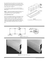
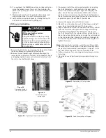
bottom horizontal wireway. (Figure 43) Motor control center
units are factory wired to their master terminal blocks.
The motor control center lead sheet, located in the informa-
tion packet, indicates the type of wiring provided for this
installation.
Field Terminations: NEMA Classes and Types
Class I Types
Class II Types
Description
A B-D B-T C
B-D B-T C
Terminals Furnished
For all control connections X X X X X X
For starter load connections
Sizes 1 thru 3 X X X X
Terminals Mounted
On control unit X X X X X X
In master terminal
compartment X X
Interwiring
Between units in the same
motor control center X X X
Figure 42
- Master Terminal Block Location
Figure 43
- Type “C” wiring terminal
Siemens Energy & Automation, Inc.
24

