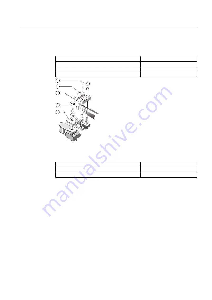
4. Make sure the terminal clamps
③
,
④
are arranged correctly for the size of the conductor.
Insert the cable into the terminal clamps. Tighten the clamping nuts
⑤
to the tightening
torque as specified in the following table.
Terminal box
Tightening torque
GT640 / 1XB1621 / 1XB1631 / 1XB1634
8 Nm
1XB7730 / 1XB7731
4 Nm
1XB7740 / 1XB7750
8 Nm
Figure 6-11
Connection using terminal clamps (schematic diagram)
5. If you have loosened the terminal body clamping bolts
②
, then retighten them with the
following torque:
Terminal box
Tightening torque
1XB1621 / 1XB1631 / 1XB1634
40 Nm
GT640 / 1XB7730 / 1XB7731 / 1XB7740 / 1XB7750
20 Nm
For terminal boxes GT640, 1XB7730 and 1XB7731, fasten the terminal element
①
using a
clamping nut M12 on the threaded stud of the terminal support with a torque of 20 Nm.
Electrical connection
6.5 Inserting and routing the cables
SIMOTICS FD 1LH1
Operating Instructions 01/2019
91
Summary of Contents for SIMOTICS FD 1LH1
Page 2: ...23 01 2019 19 26 V11 01 ...
Page 28: ...Description SIMOTICS FD 1LH1 28 Operating Instructions 01 2019 ...
Page 122: ...Operation 8 10 faults SIMOTICS FD 1LH1 122 Operating Instructions 01 2019 ...
Page 140: ...Maintenance 9 2 Corrective Maintenance SIMOTICS FD 1LH1 140 Operating Instructions 01 2019 ...
Page 162: ...Disposal 11 5 Disposal of components SIMOTICS FD 1LH1 162 Operating Instructions 01 2019 ...
Page 164: ...Service and Support SIMOTICS FD 1LH1 164 Operating Instructions 01 2019 ...
Page 168: ...Quality documents SIMOTICS FD 1LH1 168 Operating Instructions 01 2019 ...
Page 173: ......


