background image

Port assignment

Technical data

A26391-K84-Z100-1-7619

95

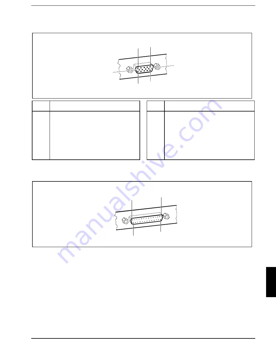
Port for external monitor

1

5

6

10

11

15

Pos.

Meaning

Pos.

Meaning

1
2
3
4
5
6
7
8

Video output red
Video output green
Video output blue
reserved
DDC ground
Video ground red
Video ground green
Video ground blue

9

10
11
12
13
14
15

+5V
logic ground
reserved
DDC data line (bi-directional)
horizontal synchronization
vertical synchronization
DDC clock signal line

Parallel interface

1

13

25

14

The parallel interface supports three transfer modes: SPP, EPP and ECP. SPP mode (standard
parallel port) is the mode traditionally used to drive a printer. EPP (Enhanced Parallel Port) and ECP
(Extended Capabilities Port) modes are transfer modes that allow transfer rates of 2 and 2.4 Mbytes/s.
These modes will only work in connection with peripheral devices which specifically support them.
Cases where these transfer modes are used are, for example, interface conversions between Parallel
and SCSI or Parallel and IDE. The pinouts are different in all three modes.

Summary of Contents for Mobile 750

Page 1: ...l data transfer You can connect peripherals such as e g scanner loudspeakers gamepads keyboard or mouse via the USB interface The notebook disposes of a infrared interface for wireless data transfer In addition the notebook has a connection port for a MobiDock or a QuickPort An audio controller two loudspeakers a microphone an audio input and output and a loudspeaker output provide your notebook w...

Page 2: ...exts in italics indicate commands or menu item Installing an ergonomic video workstation Before you set up your equipment you should select a suitable position for working at the monitor Please observe the following advices when installing a video workstation Window permissible reaching sector 600 mm edge of desk permissible reaching sector 600 mm Avoid direct and reflected glare Avoid glare from ...

Page 3: ...ant notes in the paragraph Cleaning the notebook Keep this Operating Manual together with your device If you pass on the device to third parties you should also pass on this manual Notes on installing and removing boards and modules Only qualified technicians may repair the device Unauthorized opening or incorrect repair may greatly endanger the user electric shock fire risk Boards with electrosta...

Page 4: ...maging The device is taken back after use so that it can be recycled provided that it is returned in a condition which is the result of normal use Any components not recuperated will be disposed of in an environmentally acceptable manner For devices marked with this symbol Siemens AG offers a guarantee for 36 months with a Bring in Service The guarantee starts on the day of delivery sale date by S...

Page 5: ...t interference will not occur in a particular installation If this equipment does cause harmful interference to radio or television reception which can be determined by turning the equipment off and on the user is encouraged to try to correct the interference by one or more of the following measures Reorient or relocate the receiving antenna Increase the separation between equipment and the receiv...

Page 6: ...shall be used For units which stand on floor only SJT type cord sets shall be used The cord set must be selected according to the current rating for your unit Please consult Table A for the selection criteria for power cords used in the United States and Canada Table A Cord Type Size of Conductors in Cord Maximum Current Rating of Unit SJT 18 AWG 16 AWG 14 AWG 10 Amps 12 Amps 12 Amps SVT 18 AWG 17...

Page 7: ...rom damage through mishandling The carrying bag provided protects against dust but offers no protection against jolts or impacts Protect the notebook from severe shocks and extreme temperatures e g direct sunlight in a car Before starting the journey Copy important data from the hard disk to a floppy disk Remove all data carriers e g floppy disk CD from the drives If you wish to use your notebook ...

Page 8: ...ve this job to a service technician Do not use any cleaning agents that contain abrasives or may corrode plastic Ensure that no liquid enters the notebook Wipe the casing with a dry cloth If particularly dirty use a cloth which has been moistened in mild domestic detergent and then carefully wrung out To clean the keyboard and the touchpad you can use disinfectant wipes Wipe the monitor casing wit...

Page 9: ...have been entered on the first page of the guarantee coupon booklet Should you discover that the delivery does not correspond to the delivery note notify your local sales office immediately i Do not discard the original packing material of the devices Keep it for future transportation of the drive Choosing where to set up your notebook Select a suitable location for the notebook before setting it ...

Page 10: ...in the country in which you intend to use it The notebook and the power adapter should be at least 200 mm apart Keep other objects 100 mm clear of the notebook and its power adapter Do not cover the ventilation slots in the notebook Place the notebook on a level stable surface Depending on the version your notebook will be supplied with and internal or an external power adapter External power adap...

Page 11: ...ctor on the notebook 1 Plug the power cable into the power outlet 2 A battery built into the right slot is recharged in this configuration A battery is fully charged in approximately three hours if the notebook is switched on If the notebook is switched on it will charge in roughly five to six hours i You can also make your notebook operational by connecting it to the optional power adapter or car...

Page 12: ...me installation i When you switch on your notebook for the first time the supplied software is set up and configured Please follow the instructions on the screen If you want to partition your hard disk please refer to chapter Restoring the hard disk contents under Windows 9x If you have assigned a password you must enter this when requested to do so in order to start the operating system Notes on ...

Page 13: ...approx one second Close the display of the notebook 2 so that it locks into place Indicators and input devices 4 2 1 3 5 1 6 1 LCD lock 2 LCD switch off 3 Touchpad with touchpad buttons 4 Kensington Lock device 5 Display field 6 Battery indicator right power on indicator left Only release the LCD lock when required You can protect your notebook from theft with the Kensington Lock device 3 and with...

Page 14: ...tery The arrow shows whether the battery is being charged or drained The notebook is connected to an external power source e g via the power adapter The notebook is switched to Suspend to DRAM mode The floppy disk in the floppy disk drive is being accessed You must not remove the floppy disk when this symbol is visible A drive hard disk drive CD ROM drive DVD drive or Zip drive is being accessed W...

Page 15: ... button The left and right touchpad buttons have the same functions as the left and right mouse buttons i If you attach and install an external mouse the touchpad and its buttons are disabled If you attach an external serial mouse you must select the Disabled option for the PS 2 Pointing Device field in the Main Setup This also releases interrupt 12 so that you can use it for other applications Ke...

Page 16: ...Caps Lock key activates uppercase mode CapsLK is shown in the display field The Caps Lock function causes all the characters you type to appear as uppercase In the case of overlay keys the character on the upper left on the keycap appears when that key is pressed To cancel the Caps Lock function simply press the Caps Lock key again Shift key The Shift key causes uppercase characters to appear In t...

Page 17: ...ows E Euro key The Euro key produces the Euro character Windows 98 and Windows NT5 0 Numeric keypad 7 8 9 0 U I O P J M K L _ Ö µ 7 8 9 4 5 6 1 2 3 0 1 2 1 Characters enabled when neither PadLK nor NumLK are visible in the display field 2 Characters enabled when PadLK and NumLK are visible in the display field The key 3DG 3DG 1XP 1XP enables and disables the integrated numeric keypad If the numeri...

Page 18: ...O OW OW keys instead F1 LCDOff Fn Switching monitor on off This key combination switches your notebook s display on and off Doing so does not affect any running programs F3 Standby Fn Enabling Standby mode This key combination enables Standby mode The power on indicator flashes You can cancel Standby mode by pressing any key F4 Suspend Fn Enabling Suspend mode This key combination switches the Sus...

Page 19: ...nation reduces the brightness of the display Fn Reducing display contrast If the notebook has an ADS color monitor this key combination reduces the display contrast Fn Increasing display contrast If the notebook has an ADS color monitor this key combination increases the display contrast Ctrl Break Pause Halting the current operation This key combination can be used to halt an operation instantly ...

Page 20: ...he battery symbol in the display field A battery is fully charged in approximately three hours if the notebook is switched on If the notebook is switched on the battery will charge in roughly five to six hours You can charge the battery by connecting the notebook to the AC adapter connecting the notebook to the power adapter connecting the notebook to the car adapter connecting the notebook to the...

Page 21: ...ntilation slots in the notebook Switch off the notebook Place the notebook on a level stable surface Deinstall the battery from the left slot and install it in the right slot see Removing and installing drives and batteries Place the AC adapter in the left hand slot so that the contacts enter first The connector for the AC adapter power cable must face outwards Push the AC adapter into the slot un...

Page 22: ... the battery in the slide in module 3 2 1 Open the flap of the AC adapter 1 Pull the power adapter cable somewhat out of the AC adapter 2 The power adapter cable is permanently attached to the AC adapter and cannot be completely removed from the AC adapter Close the flap of the AC adapter 3 When doing so make sure that the power adapter cable is located in the groove of the AC adapter provided and...

Page 23: ...K84 Z100 1 7619 23 1 2 3 Connect the power adapter cable of the AC adapters to the direct current socket DC IN of the notebook 1 Connect the power cable to the AC adapter 2 Plug the power cable into the power outlet 3 The power adapter indicator lights up ...

Page 24: ... notebook and its power adapter Do not cover the ventilation slots in the notebook and the power adapter Do not stand the power adapter on heat sensitive material The power adapter s AC cord may only be connected to a wall outlet if the notebook is connected to the power adapter Switch off the notebook Place the notebook on a level stable surface 1 2 3 Plug the DC output connector on the power ada...

Page 25: ...r DC IN on the notebook 1 Start the car s engine You should only use the car adapter while the car s engine is running You must not start the car s engine while the car adapter is connected to the car s electrical system Do not stand the car adapter on heat sensitive material When in operation the car adapter must be free standing and may not be covered Keep other objects 200 mm clear of the noteb...

Page 26: ...e Removing drive battery 1 2 Switch off the notebook You can leave the notebook on provided the battery is not the notebook s only power source Swing open the display Place the notebook on a level surface Press the battery s unlock button 1 The release button for drives is located on the right side Pull the battery 2 or on the right side the drive out of the slide in module Installing drive batter...

Page 27: ... force when installing or removing the floppy disk drive Make sure that no foreign objects enter the slot i The disk drive can also be removed or installed while in operation but not when the disk drive is being accessed Connecting the floppy disk drive externally Open the cover 1 Connect the floppy disk drive externally to the parallel port via an adapter cable 1 ...

Page 28: ...protected 7 Floppy disk is not write protected To insert a floppy disk push it into the drive in the insertion direction 1 until it engages The label should be facing upward To remove the floppy disk press the eject button 5 The write protect slider enables you to protect the data on the floppy disk from inadvertent overwriting or deletion To protect the data on the floppy disk from being overwrit...

Page 29: ...nlight Avoid storing a CD DVD in areas subject to high temperatures or humidity You may use both 8 cm and 12 cm CDs When using CDs DVDs of minor quality vibrations and reading errors may occur 3 2 1 1 Power on indicator 2 Insert Eject button 3 Opening for manual ejection Power on indicator The power on indicator 1 flashes when a CD DVD is inserted It goes out when the drive is ready for reading It...

Page 30: ...e CD DVD in the CD DVD tray with the labeled side facing upwards and carefully push the CD DVD into the mount or remove an inserted CD DVD Push the CD DVD tray in until you feel it locking into place Manual removal emergency removal In the event of a power failure or damage to the drive it may be necessary to manually remove the CD DVD Switch off the notebook Press a piece of wire e g a paper clip...

Page 31: ...omega installation disk with Start Run Windows 9x or File Run Windows 3 1 Follow the instructions on the screen Switch on the notebook again and start Windows Insert the Zip disk Iomega Tools in the Zip drive Follow the installation instructions displayed on the screen to finish the software installation Reinstalling the Iomega software from the Zip disk If the Zip drive of your notebook has alrea...

Page 32: ...Zip disks and the following notes Always switch your computer on before inserting a Zip disk Never use force when inserting and removing Zip disks Never use ordinary 3 5 disks or cleaning disks in your Zip drive This will damage the Zip drive Do not move the protection against accidental contact on the Zip disk Protect your Zip disk from dust mechanical vibration heat direct sunlight and strong ma...

Page 33: ... the power consumption and thus to extend the operating time of the battery In the sleep mode the speed of the disk is automatically reduced after an adjustable inactive time e g 3 minutes If the drive is accessed the speed of the disk is automatically increased again The sleep mode time for the Zip drive is controlled via the system settings of your notebook Removing the Zip disk Gently push the ...

Page 34: ... connected to the notebook PC Cards Two PC card slots CardBus or PCMCIA enable the notebook to operate two type II PC cards or one type III PC card The PC card must not consume more than 600mA at 5V or 60mA at 12V Consult the documentation supplied by the PC card s manufacturer and follow the instructions provided Never use force when inserting or removing a PC card Make sure that foreign objects ...

Page 35: ...vice drivers For further information refer to the information files e g TXT DOC WRI or HLP provided with the PC card driver diskette or the information in the Windows 9x manual You can push the PC card slot eject buttons down flush into the notebook casing Press the eject buttons until they snap in Removing PC cards 1 2 Press the eject button 1 It will project further out of the notebook s case If...

Page 36: ...crophone and loudspeaker 1 2 2 1 built in microphone 2 built in loudspeaker Your notebook contains a built in microphone 1 and a loudspeaker 2 If you attach an external microphone the built in microphone is disabled If you attach an external loudspeaker the built in loudspeaker is disabled ...

Page 37: ... little power and operates slightly slower than usual Activating In the Power Setup menu set the Power Savings field to Maximum Battery Life Set the PM Control field in the Power Setup menu to Always Enable or to Battery Powered Only Exit In the Power Setup menu set the PM Control field to Disabled Standby mode In Standby mode the notebook s system clock is suspended and its display and hard disk ...

Page 38: ... a power supply the current data is lost Activating If your notebook is in Suspend mode do not connect any external peripheral devices do not disconnect any external peripheral devices do not attempt to switch it on if the built in battery is empty do not change or remove the floppy disk if inserted do not add or remove RAM do not add or remove any PC cards Press the key combination Q Q or Hold th...

Page 39: ...eout field or In the Power Setup menu set the Power Savings field to Maximum Performance or Maximum Battery Life Hard disk s power management feature If the hard disk is not accessed for a predefined period of time its motor switches off automatically It switches on again automatically the next time the hard disk is accessed Activating In the Power Setup menu set the Power Savings field to Customi...

Page 40: ...p see chapter Settings in BIOS Setup You can change the settings using key combinations Switching between internal and external display If an external monitor is connected to your notebook you can switch between different display options You can opt to use just the notebook s internal display just the external display both the internal and the external display just the television both the internal...

Page 41: ...he security features Power Setup for setting up the power management features Docking Setup for configuring the MobiDock Boot Setup for configuring the boot sequence Exit Exiting BIOS Setup Starting BIOS Setup Restart the notebook switching on off or warm boot When the message Press F2 for Setup appears press the key i If a supervisor or user password has been defined Enter the supervisor or user ...

Page 42: ...es Example for Main menu Operating BIOS Setup Use the cursor key or Á Á to select the menu you wish to access to make changes Press the Enter key The menu is displayed on the screen Use the cursor key À À or   to select the field you wish to change Press the Space key to change the value of an entry You must enter characters in the Supervisor Password User Password and Docking Station Password f...

Page 43: ...aster None Display Device Selection LCD CRT TV Mode PAL Boot Options System Memory 640 KB Extended Memory 15 MB Item Specific Help F1 Help Select Item Space Change Values F9 Setup Defaults ESC Exit Select Menu Enter Select Sub Menu F10 Previous Values Example for Main menu System Time System Date System Time indicate the time of the device If you change the time setting enter the time in the forma...

Page 44: ...er 0 Master C 814 MB Item Specific Help Type Fixed Disk Press Enter Type Auto 814 Mb Cylinders 1579 Heads 16 Sectors 63 Maximum Capacity Multi Sector Transfers 16 Sectors LBA Mode Control Enabled 32 Bit I O Enabled Transfer Mode Fast PIO 3 Ultra DMA Mode Disabled F1 Help Select Item Space Change Values F9 Setup Defaults ESC Exit Select Menu Enter Select Sub Menu F10 Previous Values Example for the...

Page 45: ...er Multi Sector Transfers Block Transfer This field specifies the transfer mode for the IDE hard disk drive Disabled One block is transferred for each interrupt 2 Sectors 4 Sectors 6 Sectors 8 Sectors 16 Sectors The set number of blocks sectors is transferred for each interrupt This enhances performance LBA Mode Control Addressing This field enables and disables the LBA Logical Block Addressing mo...

Page 46: ...ytes s Ultra DMA Mode Access Speed This field specifies the access speed for the IDE hard disk drive Mode 0 slow access speed Mode 1 middle access speed Mode 2 fast access speed Display Device Selection This field is used to specify the display device LCD CRT The notebook s internal display and the external display are used CRT Just the external display is used LCD Just the internal display is use...

Page 47: ...e configuration is displayed when the device is switched on Disabled The configuration is not displayed when the device is switched on Floppy check Checking the disk drive This field can make the system startup faster Enabled The entire notebook configuration is checked when the notebook is switched on Disabled The disk drive is not checked in the self test when the device is switched on Quiet Boo...

Page 48: ... submenu Plug Play functionality in the Plug and Play O S field Configuration data in the Reset Configuration Data field Hard disk access in the Large Disk Access Mode field Phoenix BIOS Setup Main Advanced Security Power Docking Boot Exit Warning Setting items on this menu to incorrect values may cause your system to malfunction Integrated Peripherals PCI Devices Plug Play O S Yes Enable ACPI No ...

Page 49: ...Notebook Microphone Notebook F1 Help Select Item Space Change Values F9 Setup Defaults ESC Exit Select Menu Enter Select Sub Menu F10 Previous Values Example for the submenu Integrated Peripherals PS 2 Mouse This field determines whether the PS 2 mouse or the touchpad is enabled on the notebook Enabled The internal touchpad is activated if no PS 2 mouse is connected If a PS 2 mouse is connected wh...

Page 50: ... serial port is set to the shown address and interrupt IrDA port Infrared interface This field switches the infrared interface on or off If you wish to use infrared data transfer an infrared interface with the associated hardware must be incorporated in the device Enabled The infrared interface can be set to a certain address and interrupt in the Base I O Address field Auto The infrared interface ...

Page 51: ...terrupt Mode parallel data transmission mode This field is used to specify whether the parallel interface is to be used as a bi directional input output port or just as an output port ECP and EPP transfer modes allow faster transfer rates of 2 and 2 4 Mbytes s These modes will only work with peripheral devices which support them In addition the field Parallel must be set to 378h or 278h Bi Directi...

Page 52: ...ing If the notebook is not connected to a MobiDock Auto corresponds to the entry Both Primary The primary IDE hard disk drive controller is enabled IRQ14 is occupied Disabled The IDE hard disk drive controller of the notebook is disabled On Board Audio Audio Controller This field is used to enable and disable the built in audio controller on the system board Auto The chip is enabled and the config...

Page 53: ... enabled and the configuration is automatically carried out Enabled The joystick is enabled Disabled The joystick is disabled FM I O Base address for the joystick i This field is only visible when the Joystick field is set to enabled 200h 201h The joystick is enabled and set to the I O address displayed QuickPort Audio Audio options for QuickPort The fields set the audio options for the QuickPort ...

Page 54: ...hat the PC card controller is switched on by the system BIOS Cardbus Controller Select Settings of the PC Card Controller i This setting is only effective when a QuickPort Plus or a QuickPort S is connected If the QuickPort is not connected the controller in the notebook is always configured to the compatible address 3E0h This field specifies the order of the CardBus controller External Internal T...

Page 55: ...uld only select this setting if you are sure that the corresponding PCI board does not require an interrupt Otherwise errors may occur i PCI IRQ line 1 is used by the following PCI boards PC card controller in the notebook and in QuickPort Plus SCSI controller in the MobiDock PCI IRQ line 1 or line 2 is used by one of the PCI boards in the MobiDock This depends on the PCI board PCI IRQ line 2 is u...

Page 56: ... configuration data is reset The new configuration data is determined by means of the Plug Play functionality The mounted modules and drives are then initialized with this data i This field only takes effect if the notebook is connected to a MobiDock Large Disk Access Mode Hard disk access This field is used to specify the type of hard disk access for large hard disks more than 1024 cylinders 16 h...

Page 57: ... Exit Supervisor Password is Disabled User Password is Disabled Set Supervisor Password Press Enter Set User Password Press Enter Hard Disk Security Password on boot Disabled Diskette access User Flash Update Disabled Item Specific Help F1 Help Select Item Space Change Values F9 Setup Defaults ESC Exit Select Menu Enter Select Sub Menu F10 Previous Values Example for Security menu Supervisor Passw...

Page 58: ...one in the MobiDock If a hard disk password has already been set you must enter the set password before you can change or delete it Password on boot Password query during system startup Requirement the supervisor password or user password must be installed This field is used to specify whether the password is to be queried when the operating system is booted Disabled The password is queried only w...

Page 59: ...Docking Boot Exit PM Control Battery Powered Only Power Savings Customize Standby Timeout 5 min Auto Suspend Timeout 10 min Hard Disk Timeout 2 min Video Timeout 2 min LID Switch LCD off Battery Low Suspend Enabled Suspend Mode Save to DRAM Resume On Modem Ring OFF Resume On Time OFF Resume Time 00 00 00 Cooling Control Performance Item Specific Help F1 Help Select Item Space Change Values F9 Setu...

Page 60: ...ese entries call predefined settings thus determining the extent of energy saving Disabled None of the energy saving functions is effective Standby Timeout This field can only be changed if the PowerSaving field is set to Customize 1 2 5 10 20 30 min The system switches to standby mode after the specified time without system activity Off The PC does not switch to standby mode Auto Suspend Timeout ...

Page 61: ...specified time without system activity Off The screen does not go dark LID Switch LID mode This field specifies which mode the device is switched into when the notebook monitor is closed LCD Off The screen goes dark Standby Mode The system is switched into the standby mode see Standby Mode Suspend Mode The system state is buffered in the DRAM memory After folding open the monitor the switch on but...

Page 62: ...ime This field specifies whether the notebook is booted at a specific time The time is set in the Resume Time field This field can be operated only if Suspend Mode is set to Save to DRAM OFF The function is disabled ON The function is enabled Resume Time Setting the switch on time This field specifies whether the notebook is booted at a specific time This field can only be set if the Suspend Mode ...

Page 63: ...d Docking Station Password is Disabled Set Docking Station Password Press Enter Item Specific Help F1 Help Select Item Space Change Values F9 Setup Defaults ESC Exit Select Menu Enter Select Sub Menu F10 Previous Values Example of the Docking menu Floppy disk B Set external floppy disk drive This field shows the type of the floppy disk drive in the MobiDock Not Installed A floppy disk drive is not...

Page 64: ... IDE controller in the MobiDock Secondary The IDE drives in the MobiDock are operated on the secondary IDE channel IRQ15 Disabled The IDE controller in the MobiDock is disabled SCSI Controller Setting the MobiDock SCSI controller This field is used to enable or disable the SCSI controller in the MobiDock Enabled The SCSI controller in the MobiDock is enabled Disabled The SCSI controller in the Mob...

Page 65: ...Power Docking Boot Exit 1 Diskette Drive 2 Hard Drive 3 CD ROM Drive Item Specific Help F1 Help Select Item Space Change Values ESC Exit Select Menu Example for Boot menu Default entry 1 Diskette Drive 2 Hard Drive 3 CD ROM Drive To change this boot sequence proceed as follows Place the cursor on the entry for the drive you to which wish to move forward or back Press the function key to move the s...

Page 66: ... Defaults ESC Exit Select Menu Enter Select Sub Menu F10 Previous Values Example for menu Exit Save Changes Exit Saving and Exiting This field saves the settings you have made and exits BIOS Setup Exit Without Saving Changes This field exits BIOS Setup without saving the new settings i If you have made changes to passwords these changes are still saved Get Default Values This field reverts all set...

Page 67: ...nting unauthorized system access You can activate this protection by setting a user password in the Security menu Set User Password In addition you must select the entry Enabled in the Password on boot field Preventing unauthorized access to the hard disk drives You activate this protection when you set hard disk passwords in the Hard Disk Security submenu of the Security menu Set HD1 HD2 password...

Page 68: ... as follows Call BIOS Setup and select the Security menu see Settings in BIOS Setup You must additionally change into the Hard Disk Security submenu for the hard disk passwords Mark the Set Supervisor Password or Set User Password or Set HD password field and press the Enter key The following applies for setting a hard disk password if a hard disk password is already set you are prompted to input ...

Page 69: ...ange into the Hard Disk Security submenu for the hard disk passwords Mark the Set Supervisor Password or Set User Password or Set HD password field and press the Enter key If a password has already been assigned you will be asked to enter the old password Enter Current Password Enter the old password and press the Enter key You are asked to enter a password Enter new Password Press the Enter key t...

Page 70: ......

Page 71: ...ur hard disk prior to installation The notebook does not start after switchon If the notebook does not start after switchon this may be due to the following causes The battery is not installed correctly Switch off the notebook Check whether the battery is installed correctly in its compartment Switch on the notebook The battery is dead Recharge the battery or install a fully charged battery The po...

Page 72: ...ernal monitor stays blank If your screen remains blank this may have the following causes Monitor is switched off Switch the external monitor on Screen has been blanked Press any key to continue Brightness control is set to dark Set the brightness control to light For detailed information please refer to the Operating Manual supplied with your monitor The notebook has been configured to drive the ...

Page 73: ...aused the malfunction Close the application program or restart the notebook by switching it on off or with a warm boot The battery is dead Recharge the battery or install a fully charged battery The touchpad does not work If the touchpad does not work it can have the following reasons Incorrect setting in Setup Check whether the field PS 2 Mouse in the Main Setup is set to Enabled or to Auto Detec...

Page 74: ...k via its power adapter to a wall outlet The backup battery will charge fully in roughly two days The printer does not print Makes sure that the printer is switched on and on line see the manuals supplied with the printer Check that the printer cable connecting the notebook and the printer is connected properly Check that the correct printer driver is installed Check the submenu Integrated Periphe...

Page 75: ... the programs that were active when it switched to Suspend mode Error messages on the screen This section describes the error messages generated by the system BIOS Error messages displayed by the operating system or programs are described in the relevant manuals Diskette read failure press F1 to retry boot The inserted system disk is defective Insert another system disk Press function key No boot ...

Page 76: ...s function key Reconfigure the system If the error message is displayed again the notebook s backup battery is empty Connect the notebook via its power adapter to a grounded wall outlet or install a fresh battery The backup battery will charge fully in roughly two days Restoring the hard disk contents under Windows 9x Insert the Windows 9x startup disk into the floppy disk drive and switch the not...

Page 77: ...ver use force when installing or removing memory modules Make sure that foreign objects do not fall into the memory module compartment The main memory of your notebook can be expanded to 32 192 Mbyte using up to three 32 or 64 Mbyte memory modules The notebook will not start without memory modules as no fixed main memory is installed Installing removing memory expansion Switch off the notebook Rem...

Page 78: ...the slot 1 Carefully flap the memory module down 2 until you feel it latch in place Install the other memory modules in the same way In order to remove memory modules 1 1 2 Carefully push the two mounting clips outwards 1 The memory module flaps upwards Slide the memory module out of its location 2 Remove the other memory modules in the same way ...

Page 79: ...ce the cover on its mounting location 1 and flap it into place on the underside of the notebook 2 Fasten the cover with the screw 3 Place the notebook bottom down on a flat surface Reconnect the cables that you disconnected before Swing open the display Refit the battery ...

Page 80: ......

Page 81: ...Connecting cables Turn off all power and equipment switches Pull all power plugs out of the grounded power outlets Connect all the cables to the notebook and the external devices Please observe under all circumstances the information provided in the chapter Important notes Plug all data communication cables into the utility sockets Plug all power cables into the grounded power outlets Disconnectin...

Page 82: ... port you must first open the port cover Flap the port cover down Connect the desired device IR DC IN Microphone jack Audio input Line in Audio output Line out Audio output Loudspeaker USB Universal Serial Bus PS 2 mouse port or keyboard port DC IN DC socket IR IR Port Serial port Video connector Connection for QuickPort or MobiDock Parallel interface TV out ...

Page 83: ...16 bits If you wish to use a resolution greater than 640 x 480 you must load the relevant display drivers see the manuals supplied with your display Plug the data cable of the monitor into the monitor port Connect the power cable of the external monitor to a power outlet and switch on the monitor Switch on the notebook Configure the display output in the Display Device Selection field in Main Setu...

Page 84: ...ure that no PC cards or extracting tools for PC cards are projecting from the notebook No power adapter may be connected when you dock the MobiDock onto the notebook If the notebook is connected to a MobiDock in which a PCI VGA board is installed the notebook s display is always switched off In case of problems with the display output on the external monitor check the settings in the Display Devic...

Page 85: ...etup You can change the setting in the IrDA Port field in the Integrated Peripherals submenu in Advanced Setup i The infrared interface can only be used when the infrared interface is enabled in the IrDA Port field in the Integrated Peripherals submenu in Advanced Setup Set up the infrared transmitter and receiver as illustrated above The devices may be no more than one meter apart The infrared in...

Page 86: ......

Page 87: ...drives Floppy disk drive for 3 1 2 inch floppy disks hard disk drive 2 5 inch 12 7 mm height CD ROM drive twenty speed or more Display Display diagonal LCD TFT ADS Resolution colors LCD TFT 12 1 LCD ADS 13 LCD TFT 13 3 Backlit liquid crystal transmissive display LCD 30 7 cm 12 1 inch XGA Overhead Display 33 0 cm 13 0 inch XGA ADS 33 8 cm 13 3 inch XGA 1024x768 262 144 colors 18 bit Screen controll...

Page 88: ... interface Fast IrDA USB Universal Serial Bus 6 pin mini DIN female connector female connector 240 pin 25 pin female connector bi directional EPP ECP capable female connector 15 pin 9 pin male connector 16550 compatible connector stereo connector mono connector stereo connector stereo Power consumption 50 W max notebook on with battery charging Permissible ambient temperature during operation Tran...

Page 89: ...max rated current 19 V 2 6 A CD ROM drive Supported CD formats CD Digital Audio CD ROM Mode 1 and Mode 2 CD ROM XA Mode 2 Form 1 and Form 2 CD I Mode 2 Form 1 and Form 2 CD I Ready CD bridge Photo CD Single and Multisession Video CD Laser Class 1 Laser Product Type Wave length Power output Semiconductor GaA As 780 nm 5 mW max DVD drive Supported DVD CD formats DVD 5 4 377 Gbyte DVD 9 7 959 Gbyte D...

Page 90: ...ontrol Interface 800h 807h 810h 817h 820h 827h 830 837h IRQ 5 LPT IRQ 7 LPT IRQ 9 IRQ 10 IRQ 11 1 DMA DMA 1 DMA 0 DMA 3 2 DMA DMA 3 DMA 0 DMA 1 Parallel port LPT 378h 37Fh 378h 37Fh 3BCh 3C5h 278h 27Fh IRQ 7 IRQ 5 IRQ 7 IRQ 5 DMA 1 or DMA 3 in ECP mode 1 Serial port COM 3F8h 3FFh 2F8h 2FFh 3E8h 3EFh 2E8h 2EFh IRQ 4 COM1 IRQ 3 COM2 IRQ 4 COM3 IRQ 3 COM4 2 Serial port COM Fast IrDA 2F8h 2FFh 3E8h 3E...

Page 91: ...020h 021h 0A0h 0A1h 2 Floppy disk drive controller 3F0h 3F5h 3F7h 6 2 System CMOS Realtime clock 070h 071h 8 PC card controller Cirrus CL PD 6832 automatically defined Shared IRQ USB controller automatically defined Shared IRQ Synaptics touchpad 12 Numeric processor 0F0h 0FFh 13 Intel 82371AB PCI bus Master IDE controller 1F0h 1F7h 3F6h 14 DMA controller 000h 00Fh 081h 08Fh 0C0h 0DFh 4 PCI bus CF8...

Page 92: ...rd PCMCIA cards max 1x TypIII or 2x TypII I O cards modem network board COM SCSI etc memory cards e g SRAM FLASH ATA cards e g Harddisk Sundisk PC cards require an IRQ no shared IRQ I O addresses and or a memory area and possibly DMA see also the documentation on the PC card BIOS SETUP PnP Plug and Play Shared IRQ Several PCI components can share one free ISA IRQ assignment of the IRQs is automati...

Page 93: ...ent The assignment of the external ports are as follows DC jack DC IN 1 2 Pos 1 2 Meaning 0 V 19 V Port for external keyboard or PS 2 mouse Pos 1 2 3 4 5 6 Meaning Data free 0 V 5 V Clock free TV out socket 1 2 3 4 Pos 1 2 3 4 Meaning 0 V 0 V SVideo_Y_FBAS_MUX SVideo_COL ...

Page 94: ...Data DTR Data Terminal Ready Signal Ground DSR Data Set Ready RTS Request to Send CTS Clear to Send Ri Ring Indicator Data Carrier Detect Receive Data Transmit Data Data Terminal Ready Signal Ground Data Set Ready Request to Send Clear to Send Ring Indicator USB port 1 Pin Signal name Meaning 1 2 3 4 VCC DATA_NEGATIVE DATA_POSITIVE GND VCC of the Notebook Data Data Ground ...

Page 95: ...ock signal line Parallel interface 1 13 25 14 The parallel interface supports three transfer modes SPP EPP and ECP SPP mode standard parallel port is the mode traditionally used to drive a printer EPP Enhanced Parallel Port and ECP Extended Capabilities Port modes are transfer modes that allow transfer rates of 2 and 2 4 Mbytes s These modes will only work in connection with peripheral devices whi...

Page 96: ... error Reset initialize Printer selection Ground Pinout in EPP mode Enhanced Parallel Port Pos Signal name Meaning 1 2 9 10 11 12 13 14 15 16 17 18 25 Write Data Lines Intr Wait reserved reserved DStrb reserved reserved AStrb Ground Output Input output Input Input Output Output Pinout in ECP mode Enhanced Capabilities Port Pos Signal name Meaning 1 2 9 10 11 12 13 14 15 16 17 18 25 HostClk Data Li...

Page 97: ...3 4 5 6 7 8 9 10 11 12 13 14 15 16 17 18 22 23 24 25 5V INDEX TRK0 WP RDATA DSKCHG MSEN0 DRATE0 MSEN1 DR1 MTR1 WDATA WGATE DENSEL HEAD DIR STEP Ground 5V PNF Ground Output Supply voltage Input Input Input Input Input Input Output Input Output Output Output Output Output Output Output Output Output Supply voltage Input Signal is low active ...

Page 98: ...d input devices 13 Display field 14 Touchpad and Touchpad Keys 15 Keyboard 15 Key combination 18 The battery 20 Charging caring for and maintaining the battery 20 Connecting the AC adapter 21 Using AC adapter as external power adapter 22 Connecting the power adapter 24 Connecting the car adapter 25 Removing and installing drives and batteries 26 Floppy disk drive 27 Connecting the floppy disk driv...

Page 99: ...s privilege for disk drive 58 Flash update Permission for BIOS update 58 Power menu Setting energy saving functions 59 PM Control Effectiveness of the energy saving functions 59 Power Savings Extent of energy saving functions 60 Standby Timeout 60 Auto Suspend Timeout Suspend mode 60 Hard Disk Timeout Hard disk energy saving function 61 Video timeout Energy saving functions for the monitor 61 LID ...

Page 100: ...ssed 74 Acoustic warnings 75 Error messages on the screen 75 Restoring the hard disk contents under Windows 9x 76 System expansions 77 Memory expansion 77 Installing removing memory expansion 77 Connecting external devices 81 Port covers and connectors 82 Connecting devices with serial or parallel port 83 Connecting an external monitor 83 Connecting the mouse 83 Connecting an external keyboard 84 ...

Page 101: ...e durch Kopieren oder ähnliche Verfahren Zuwiderhandlungen verpflichten zu Schadenersatz Alle Rechte vorbehalten insbesondere für den Fall der Patenterteilung oder GM Eintragung Microsoft MS MS DOS und Windows sind eingetragene Warenzeichen der Microsoft Corporation Die übrigen erwähnten Hard und Softwarenamen sind Handelszeichen und oder Warenzeichen der jeweiligen Hersteller Liefermöglichkeiten ...

Reviews: