Commissioning
Starting up the radio gateway on the detector line
6
60 | 82
Building Technologies
009865_m_en_--
Fire Safety
2015-11-06
Logging on more radio detectors
1. Repeat the process for all other radio detectors on the same radio gateway.
2. When the field strength flashing has stopped, exit the radio gateway's
configuration mode by briefly pressing the button.
a
The radio gateway is then in normal operation and all LEDs are off.
●
After 15 minutes without any action, the radio gateway automatically switches
from configuration operation to normal operation.
●
After 30 radio detectors have logged on, the radio gateway automatically
switches to normal operation.
See also
2
Resetting the DOW1171 to delivery status [
2
Resetting the SMF6120 to delivery status [
2
2
6.4 Starting up the radio gateway on the detector line
Once all the radio detectors of a radio cell have been logged on to the radio
gateway in battery mode, the FDnet detector line can be started up.
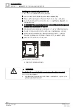
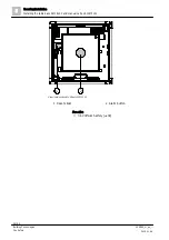
Connection diagram for FDnet detector line
Procedure:
1. Connect the FDnet detector line cable to the 'LINE' spring clips.
2. Start the FDnet detector line up again. You will find instructions on
commissioning the detector line in the corresponding system and control panel
documentation.
For FS20: Document 009052
Assignment of the detector serial number to FC20xx:
The last three digits match. If e.g., the serial number of the detector is '80840349',
the ID on the FC20xx control panel is defined as follows:
..........349
In terms of topology, the radio detectors logged onto the radio gateway are in a
stub. The stub passes through the FDnet detector line between the FDCW221
and the integrated line separator FDCL221 of the radio gateway. The order in
which the radio detectors log on determines the order on the stub.
LINE
+
+
_
_
+
_
SHIELD


