background image

14

SE 80/185 T - SE 100/185 T - SE 130/250T


1.0.1- 2008

Model

Voltage Nominal 

current 

draw

Min. battery  

CCA

>7m total + & - 7-14m total + & - 15-21m total + & - 22-28m total + & - 28-35m total + & - 36-45m total + & -

Min.

Rec. Min.

Rec.

Min.

Rec.

Min.

Rec.

Min.

Rec.

Min.

Rec.

SE80/185T

12 V

530 A

DIN: 550 

SAE:1045

mm

AWG

60 

2/0

70 

2/0

95 

3/0

2x 70  

2x 2/0

2x 70 

2x 2/0

2x 95 

2x 2/0

2x 95 

2x 3/0

270*

2x 120 

2x 4/0

340*

NA

NA

24 V

260 A

DIN: 300 

SAE: 570

mm

AWG

25 

1

35 

1

35 

1

50 

1/0

60 

2/0

70 

2/0

70 

2/0

95 

3/0

95 

3/0

120 

4/0

120 

4/0

2x 95 

2x 3/0

SE100/185T

SE130/250T

12 V

740 A

DIN: 750 

SAE: 1425

mm

AWG

95 

3/0

95 

3/0

2x 70 

2x 2/0

2x 95 

2x 3/0

2x 95

2x 3/0

280*

250* 

375*

NA

NA

NA

NA

24 V

340 A

DIN: 400 

SAE: 760

mm

AWG

35 

1

50 

1/0

50 

1/0

70 

2/0

60 

2/0

95 

3/0

95 

3/0

120 

4/0

120

4/0

2x 95 

2x 3/0

2x95

2x 3/0

2x 120 

2x 4/0

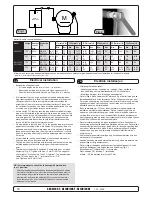
Minimum and recommended cable dimensions can be identical due to  safety margins and cable heat considerations for short cable lenghts.

* Minimum or recommended cable cross section in mm

2

Battery & cable recommendations:

Elektrisk installasjon

N


Forklaring til elektrisk tabell

  - Kabellengder til kabelen, og - kabelen (Frem og tilbake).
  - Min. batterikap. som kaldstartkapasitet (CCA), ikke Ampere.
  - Bruk trege sikringer for å forebygge spenningsfall.


Det er viktig å bruke kabler som er store nok, og et batteri med god ka-

ldstartkapasitet for å drive thrusteren. Det er Volten som kommer frem 

til motoren under kjøring som bestemmer turtallet til motoren og dermed 

også skyvekraften. Vær vennlig og  jamfør listen over for minimum 

anbefalte kabel, og batteristørrelse.


En hovedstrømbryter (*C) som ikke medfører stor spenningsfall må 

installeres på thrusterens plusskabel. Det bør være mulig å skru av 

strømmen til thruster uavhengig av resten av det elektriske systemet, 

når man ikke er om bord, eller i et nødstilfelle. Bryteren bør plasseres 

på et tilgjengelig sted, og båtens instruksmanual må ta for seg at denne 

skal skrus av slik som de andre hovedbrytere.


Det må installeres sikring på pluss strømkabelen for å beskytte mot 

kortslutning av hovedstrømkablene. Sikringen bør være av høy kvalitet, 

noe som vanligvis betyr at de er fysisk store, for å unngå spenningsfall 

som ofte er resultatet av å bruke mindre, enklere sikringer. Sikringen 

skal være en treg type som tåler amper trekket til elektromotoren i 

minimum 5 min.


En kretsbryter kan erstatte sikringen og hovedstrømbryteren hvis den 

har de samme funksjonene.


Kabelendene kan må påmonteres terminaler og disse må isoleres mot 

alt som ikke er riktig kontaktpunkt. 


Det er viktig att kabelsko trekkes korrekt fast på koblingsbolt. Kontra 

mutter på koblingsbolt må holdes fast ved tiltrekking (Fig. 2).  

Minus kabelen (*A) tilkobles A1 (-) terminalen. 

Pluss kabelen (*B) tilkobles "+" terminalen. 

ø10mm / 3/8’’på motoren dra til med 15 Nm.

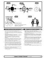
Electrical installation

GB

Battery

12V or 24V

+

-

M

-

+

*D

*C

Fig. 1

Fig. 2

  Explanation of electrical table 

  -   All cable lengths are the total of + and - (to and from). 

  -   Battery size is stated as minimum cold crank capacity, not Ah. 

  -   Use slow fuse rated to hold stated Amp-Draw for min. 5 minutes.

  It is important that you use a good cable size and batteries with a 

  high cranking capacity to feed the thruster, because it is the actual 

  voltage at the motor while running the thruster that decides the  

  output rpm of the motor and thereby the actual thrust. Please see  

  the list below for advised min. sizes of cables and batteries. You can  

  of course use larger cables for even better results.

  A main switch (*C) that can take the load without noticeable voltage 

  drop must be installed in the main positive lead so the power for the  

  thruster can be turned off independent of the rest when not on board  

  or in emergencies. This should be placed in an easy accessible  

  place and the boats instructions should inform that this should be  

  turned off like the boat’s other main switches.

  We also advice to install a fuse (*D) in the positive lead for protection  

  against short circuiting of the main cables. This fuse should be of a  

  adequate quality which normally means that it is physically large as  

  these have less voltage drop than the simple / small ones. It should  

  be of the slow type and sized to take the amperage draw for at least  

  5 minutes.

  A circuit breaker can be used instead of the fuse and main power 

  switch as long as the functionality is the same. 

  The cable ends must be fitted with terminals and these must be well 


  isolated against contact with anything but the proper connection  

  point.

  Terminals must be properly tightened. Secure/hold inner nut when  

  tightening (Fig. 2). Tighten with max: 15 Nm/11lb/ft.The negative/ 

  minus cable (*A) connects to the A1 (-) terminal. The positive/plus  

  cable (*B) connects to the “+” terminal: ø10mm / 3/8" 


  bolt. Tighten with 15 Nm/11lb/ft.

NB! Very important to check the following with mainswitch 

in off   position:

  After all electrical connections have been completed check with an 

  ohm meter that there is no electrical connection between electro- 

  motor body and positive terminal on the motor and between the  

  electromotor body and the negative (A1) terminal on the motor.  

  If you feel unsure on how to perform this check, contact skilled  

  personnel for guidance. 

Summary of Contents for SE 130/250T

Page 1: ...tion and user s manual GB N Installasjons og brukermanual Made in Norway Sleipner Motor AS 2008 SLEIPNER MOTOR AS P O Box 519 N 1612 Fredrikstad Norway Tel 47 69 30 00 60 Fax 47 69 30 00 70 w w w s i...

Page 2: ...og servise 21 Problemer og l sninger 22 Garantierkl ring 23 Reservedelsliste 24 Servicesentere 28 Installation instructions Technical specifications 3 Planning important precautions 4 Tunnel installa...

Page 3: ...IC IMPERIAL 4 SP 75 Ti SP 95 Ti SP 125 Ti 2 5 1 2007 Technische Daten D C Waterline A F Motor Custom made reversible DC motor Gearhouse Seawater resistant bronze Ballbearing at propellershaft and comb...

Page 4: ...re necessary acquaintance with this product The thruster must NOT be installed in compartments that require ignition proof electric equipment If necessary make a separate compartment The electromotor...

Page 5: ...m glich Fig 1 Um einen m glichst gro en Abstand vom Drehpunkt des Schiffes zu erreichen ist der Sidepower m glichst weit vorne einzubauen Eine Vergr erung des Abstandes vom Drehpunkt des Schiffes hat...

Page 6: ...e Schubkraft und reduzieren das Ger uschniveau Der Bereich Tunnelende Au enseite des Rumpfes ist soweit m glich abzurunden Der optimale Wert f r den Radius dieser Rundung betr gt 10 des Tunneldurchmes...

Page 7: ...ance and minimum noise For more information on how to practically do this see page 20 14 SP 75 Ti SP 95 Ti SP 125 Ti 2 5 1 2007 Segelboote und sehr schnelle Booten k nnen gelegentlich durch auf die r...

Page 8: ...he hull 16 SP 75 Ti SP 95 Ti SP 125 Ti 2 5 1 2007 Segelboote weisen h ufig einen Rumpf in Rennform auf was einen sehr flachen Rumpf im Bugbereich bedeutet Es ist daher schwierig oder fast unm glich de...

Page 9: ...olyes ter glassfiber matte s rg for og lage en blanding av polyester og glass fiber som fylles i dette Tunnel installation R D Fig 1 Fig 3 Fig 4 Fig 2 GB We recommend that a professional does the fibr...

Page 10: ...ert braket kan for r sake svikt i girhus GB Fig 1a Fig 3 Fig 2 Fig 1b Fig 1c Fig 1d Fig 1 Soften the edges with a radius of 10 of the tunnel diameter Fig 1a or make a slope with a length of 10 15 of t...

Page 11: ...easurements Place the thruster in the boats centreline with the bolt hole as the centre Fig 1 It is absolutely necessary that all holes are in line with the tunnels centreline to ensure precise instal...

Page 12: ...ue til sinkanode 2 Sinkanode 3 L semutter til propell 4 Skive til propell 5 Drivpinne for propell 5 3 2 1 4 Locktite Fitting propeller s GB 1 Push the propeller onto the shaft carefully rotate the pro...

Page 13: ...propel lers to prevent growth of barnacles or similar which would reduce the performance dramatically Do not paint the propeller shaft the zincan odes or the end face of the gearhouse NB Do not run t...

Page 14: ...t som ikke er riktig kontaktpunkt Det er viktig att kabelsko trekkes korrekt fast p koblingsbolt Kontra mutter p koblingsbolt m holdes fast ved tiltrekking Fig 2 Minus kabelen A tilkobles A1 terminale...

Page 15: ...Control panel and control leads GB 1 2 3 4 2 1 3 4 Pin 4 Pin 3 Pin 2 Pin 4 Pin 3 Pin 2 M 12 or 24V SLEIPNER SID EPO W ER THRUSTER OFF ON ON SLEIPNER SID EPO W ER THRUSTER OFF ON ON Control panel insta...

Page 16: ...A2 A1 Fuse 9 6 8 1 2 4 5 red grey blue black grey blue brown red 6 1232i Electronic control box Thermal switch Battery 12V or 24V Battery main switch M 4 3 2 1 3 red red black 7 white NB Make sure to...

Page 17: ...onic interface box 6 1232i A2 A1 4 pin AMP connector On Motor 4 2 1 3 Fuse Battery main switch 1 5 4 2 6 8 9 red grey sig blue sig black red grey sig blue sig brown 3 red Fused inside 1A black 7 white...

Page 18: ...he gearhouse and motorbracket together are tightened correctly The bolts holding the electromotor to its bracket are tightened correctly Checklist GB The thruster has been installed as per the instruc...

Page 19: ...in use The maximum continues usage time of the electrical thruster is approximately 3 minutes The electromotor has a built in thermal cut off switch that will shut off the electromotor if it is overh...

Page 20: ...n Thruster How to use Sidepower thrusters GB How to use a bowthruster 1 Turn main power switch for the bowthruster on Always turn off the main power switch when not onboard 2 Please take some time to...

Page 21: ...e from inside the boat 5 blade skew propeller for ultimate performance Oil filled gearhouse Changeable zincanode protects gear house from corrosion in seawater Fastening screw for zincanode Zincanode...

Page 22: ...is ok and measure that there is contact through the magnetising spools of each side of the solenoid measure between the red and blue on one side and red and grey on the other side with an Ohm meter I...

Page 23: ...kt mellom disse m releet skiftes ut Er spenningen lavere en 10 5V 21V vil thrusteren sunke i turtall og skyvekraften senkes Thrusteren vil ha lav skyvekraft hvis en eller flere b rster ikke f r trykk...

Page 24: ...purchase price Purchaser must submit a statement in writing from a professional boating equipment supplier that the installation instructions of the Installation and Operation Manual have been complie...

Page 25: ...6 1232i 16 Solenoid bracket kit 6 0135 6 0135 15 Key for eletric motor shaft 10 1440 10 1440 14 Electric motor N A N A 13 Brush springs for motor kit 6 0170 12 6 0170 24 12 Brushes for motor kit 6 01...

Page 26: ...1232i 16 Solenoid bracket kit 9 0135 12 10 0140 24 15 Key for eletric motor shaft 10 1440 10 1440 14 Electric motor N A N A 13 Brush springs for motor kit 8 0170 12 8 0170 24 12 Brushes for motor kit...

Page 27: ...al wiring loom 15 1273B 6 1226B 17 Electronic control box 6 1232i 6 1232i 16 Solenoid bracket kit 9 0135 12 10 0140 24 15 Key for eletric motor shaft 10 1440 10 1440 14 Electric motor N A N A 13 Brush...

Page 28: ...215 www imnasa com imnasa imnasa com Sweden Sleipner AB Str mstad Tel 46 526 629 50 Fax 46 526 152 95 www sleipnerab se Switzerland Marine Parts Technics AG Volketswil Tel 41 1 997 40 90 Fax 41 1 997...

Reviews: