background image

 13

SE 80/185 T - SE 100/185 T - SE 130/250T


1.0.1- 2008

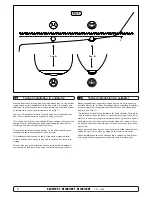
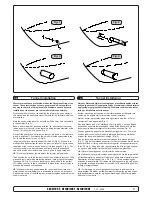
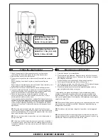
Fig. 1

Fig. 2

Montering av elektromotor

N

Fitting the electromotor

GB

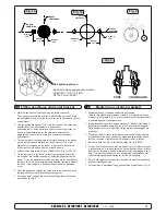
Bolt tightening force (4x):

SE80/100: 33 Nm (24 lb/ft)
SE130: 33 Nm (24 lb/ft)

Bolt tightening force (2x):

SE80/100: 17 Nm (12,4 lb/ft)
SE130: 33 Nm (24 lb/ft)

1. Check if the springs for the brushes sit correctly on the brushes  

(see through the metal web around the top of the electromotor). 

2. Remove the 4 bolts in the motor bracket.

3. Place the motor gently on the motor bracket. Be careful, the motor is 

heavy! 

  Ensure that key on axle and keyway in one-piece coupling are 

aligned. 

  Ensure that you are placing the motor so that the cable terminals  on it 

are available for electric installation later.

4. Fasten the motor to the bracket with the 4 bolts and tighten them.

5. If you are installing the motor in an angle of more than 30 degrees  

off a vertical position, the electromotor needs a separate/additional  

support. See illustration in the measurements drawings.

6. Check the drive system by turning the propeller, it will be a little  

hard to turn (because of the gear reduction and the motor), but you 

should easily be able to turn it by hand.

  In some cases (shallow installation or workboat/fishingboat only) we rec

-

ommend to protect the propeller by mounting a grid in the tunnel opening 

(Fig. 2). It is important to keep a grid to a minimum and as streamlined 

for the thruster’s waterflow as possible, as it will decrease the effect of 

the thruster. Do not use Circular profile steel as it will decrease thrust 

significantly.


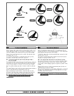
NB!

 Paint the gearhouse and propeller with antifouling for propel-

lers to prevent growth of barnacles or similar which would reduce the 

performance dramatically. Do not paint the propeller shaft, the zincan-

odes or the end face of the gearhouse.


NB! 

Do not run the thruster for more than very short bursts without 

being in the water.

  NB! 

 If the boat is still being built when the electromotor is installed, it 

must be covered up to avoid dust from the building going into the mo-

tor and the solenoids. This cover must be removed before the thruster 

is being used.

1.  Fjern de 4 boltene i i motorbraketten. 

2.  Plasser motoren på braketten. Plasser motoren slik at de releene er 

tilgjengelige for tilkobling senere. Ta hensyn til at motoren er tung når 

den bæres og håndteres.


Sjekk at kilespor i gummigobling og kile på aksel er på linje.

3.  Fest motoren til braketten med de fire boltene (Fig. 1).

4.  Hvis motoren monteres i en vinkel på mer enn 30

o

 fra loddrett, trenger 

den separat/ekstra støtte. Jamfør tekniske tegninger.

5.  Sjekk at børstefjærene sitter korrekt på børstene (gjøres ved å se 

gjennom gitteret på siden av motoren).

I visse tilfeller (ved grunne installasjoner, fiske / arbeidsfartøy fartøy) 

anbefaler vi å beskytte propell og girhus ved å montere et gitter foran 

tunnelåpningene (Fig. 2). Det er da meget viktig å beholde strømlinjefor

-

men, og å begrense gitteret til et minimum. Feil installasjon kan begrense 

skyvekraften med 10%.

NB !

 Påfør bunnstoff på girhus og propell for å unngå vekst som kan virke 

sterkt hemmende på thrusterens effekt. Sinkanoder propellaksling og 

tetninger skal ikke stoffes.

NB !

 Thrusteren må kun kjøres i meget korte perioder når den ligger på 

land.

NB !

 Hvis båten fortsatt er under bygging når thrusteren blir montert må 

motoren dekkes til for å unngå at støv og lignende trenger inn i girhus og 

elektromotor. Dekket må fjernes før motoren tas i bruk.

Summary of Contents for SE 130/250T

Page 1: ...tion and user s manual GB N Installasjons og brukermanual Made in Norway Sleipner Motor AS 2008 SLEIPNER MOTOR AS P O Box 519 N 1612 Fredrikstad Norway Tel 47 69 30 00 60 Fax 47 69 30 00 70 w w w s i...

Page 2: ...og servise 21 Problemer og l sninger 22 Garantierkl ring 23 Reservedelsliste 24 Servicesentere 28 Installation instructions Technical specifications 3 Planning important precautions 4 Tunnel installa...

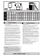
Page 3: ...IC IMPERIAL 4 SP 75 Ti SP 95 Ti SP 125 Ti 2 5 1 2007 Technische Daten D C Waterline A F Motor Custom made reversible DC motor Gearhouse Seawater resistant bronze Ballbearing at propellershaft and comb...

Page 4: ...re necessary acquaintance with this product The thruster must NOT be installed in compartments that require ignition proof electric equipment If necessary make a separate compartment The electromotor...

Page 5: ...m glich Fig 1 Um einen m glichst gro en Abstand vom Drehpunkt des Schiffes zu erreichen ist der Sidepower m glichst weit vorne einzubauen Eine Vergr erung des Abstandes vom Drehpunkt des Schiffes hat...

Page 6: ...e Schubkraft und reduzieren das Ger uschniveau Der Bereich Tunnelende Au enseite des Rumpfes ist soweit m glich abzurunden Der optimale Wert f r den Radius dieser Rundung betr gt 10 des Tunneldurchmes...

Page 7: ...ance and minimum noise For more information on how to practically do this see page 20 14 SP 75 Ti SP 95 Ti SP 125 Ti 2 5 1 2007 Segelboote und sehr schnelle Booten k nnen gelegentlich durch auf die r...

Page 8: ...he hull 16 SP 75 Ti SP 95 Ti SP 125 Ti 2 5 1 2007 Segelboote weisen h ufig einen Rumpf in Rennform auf was einen sehr flachen Rumpf im Bugbereich bedeutet Es ist daher schwierig oder fast unm glich de...

Page 9: ...olyes ter glassfiber matte s rg for og lage en blanding av polyester og glass fiber som fylles i dette Tunnel installation R D Fig 1 Fig 3 Fig 4 Fig 2 GB We recommend that a professional does the fibr...

Page 10: ...ert braket kan for r sake svikt i girhus GB Fig 1a Fig 3 Fig 2 Fig 1b Fig 1c Fig 1d Fig 1 Soften the edges with a radius of 10 of the tunnel diameter Fig 1a or make a slope with a length of 10 15 of t...

Page 11: ...easurements Place the thruster in the boats centreline with the bolt hole as the centre Fig 1 It is absolutely necessary that all holes are in line with the tunnels centreline to ensure precise instal...

Page 12: ...ue til sinkanode 2 Sinkanode 3 L semutter til propell 4 Skive til propell 5 Drivpinne for propell 5 3 2 1 4 Locktite Fitting propeller s GB 1 Push the propeller onto the shaft carefully rotate the pro...

Page 13: ...propel lers to prevent growth of barnacles or similar which would reduce the performance dramatically Do not paint the propeller shaft the zincan odes or the end face of the gearhouse NB Do not run t...

Page 14: ...t som ikke er riktig kontaktpunkt Det er viktig att kabelsko trekkes korrekt fast p koblingsbolt Kontra mutter p koblingsbolt m holdes fast ved tiltrekking Fig 2 Minus kabelen A tilkobles A1 terminale...

Page 15: ...Control panel and control leads GB 1 2 3 4 2 1 3 4 Pin 4 Pin 3 Pin 2 Pin 4 Pin 3 Pin 2 M 12 or 24V SLEIPNER SID EPO W ER THRUSTER OFF ON ON SLEIPNER SID EPO W ER THRUSTER OFF ON ON Control panel insta...

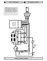
Page 16: ...A2 A1 Fuse 9 6 8 1 2 4 5 red grey blue black grey blue brown red 6 1232i Electronic control box Thermal switch Battery 12V or 24V Battery main switch M 4 3 2 1 3 red red black 7 white NB Make sure to...

Page 17: ...onic interface box 6 1232i A2 A1 4 pin AMP connector On Motor 4 2 1 3 Fuse Battery main switch 1 5 4 2 6 8 9 red grey sig blue sig black red grey sig blue sig brown 3 red Fused inside 1A black 7 white...

Page 18: ...he gearhouse and motorbracket together are tightened correctly The bolts holding the electromotor to its bracket are tightened correctly Checklist GB The thruster has been installed as per the instruc...

Page 19: ...in use The maximum continues usage time of the electrical thruster is approximately 3 minutes The electromotor has a built in thermal cut off switch that will shut off the electromotor if it is overh...

Page 20: ...n Thruster How to use Sidepower thrusters GB How to use a bowthruster 1 Turn main power switch for the bowthruster on Always turn off the main power switch when not onboard 2 Please take some time to...

Page 21: ...e from inside the boat 5 blade skew propeller for ultimate performance Oil filled gearhouse Changeable zincanode protects gear house from corrosion in seawater Fastening screw for zincanode Zincanode...

Page 22: ...is ok and measure that there is contact through the magnetising spools of each side of the solenoid measure between the red and blue on one side and red and grey on the other side with an Ohm meter I...

Page 23: ...kt mellom disse m releet skiftes ut Er spenningen lavere en 10 5V 21V vil thrusteren sunke i turtall og skyvekraften senkes Thrusteren vil ha lav skyvekraft hvis en eller flere b rster ikke f r trykk...

Page 24: ...purchase price Purchaser must submit a statement in writing from a professional boating equipment supplier that the installation instructions of the Installation and Operation Manual have been complie...

Page 25: ...6 1232i 16 Solenoid bracket kit 6 0135 6 0135 15 Key for eletric motor shaft 10 1440 10 1440 14 Electric motor N A N A 13 Brush springs for motor kit 6 0170 12 6 0170 24 12 Brushes for motor kit 6 01...

Page 26: ...1232i 16 Solenoid bracket kit 9 0135 12 10 0140 24 15 Key for eletric motor shaft 10 1440 10 1440 14 Electric motor N A N A 13 Brush springs for motor kit 8 0170 12 8 0170 24 12 Brushes for motor kit...

Page 27: ...al wiring loom 15 1273B 6 1226B 17 Electronic control box 6 1232i 6 1232i 16 Solenoid bracket kit 9 0135 12 10 0140 24 15 Key for eletric motor shaft 10 1440 10 1440 14 Electric motor N A N A 13 Brush...

Page 28: ...215 www imnasa com imnasa imnasa com Sweden Sleipner AB Str mstad Tel 46 526 629 50 Fax 46 526 152 95 www sleipnerab se Switzerland Marine Parts Technics AG Volketswil Tel 41 1 997 40 90 Fax 41 1 997...

Reviews: