


23
8024252/AE00/V1-0/2020-07| SICK
O P E R A T I N G I N S T R U C T I O N S | ZIRKOR200 Ex-D
Subject to change without notice
INSTALLATION
5
5.3
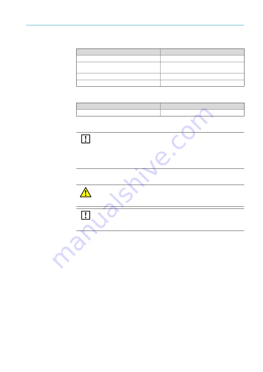
Tools required
5.4
Material required
5.5
Preparing the measuring point
5.6
Transport
The device must be lifted and transported by at least two persons.
Tools required
Required for
Allen key set
Terminal release
Phillips screwdriver set
Opening the probe enclosure cover
Removing covers in the electronics housing
Ferrule pliers
Cable preparation
Wire stripper
Cable preparation
Material required
Required for
Ferrules
Cable preparation
NOTICE:
Basis for determining the measuring point:
●
Preceding project planning (e.g., based on the SICK application questionnaire)
●
Regulations of local authorities
Responsibility of the plant operator
●
Determining the measuring point
●
Preparing the measuring point
DANGER: Danger of explosion through electrostatic charges
There is a danger of explosion due to sparks caused by electrostatic charge, for example
during transport or when unpacking the probe and electronics.
▸
Only transport and unpack in Ex-free area.
NOTICE:
The device may only be transported and assembled by competent persons who, based
on their training and knowledge as well as knowledge of the relevant regulations, can
assess the tasks given and recognize the dangers involved.


