background image


36(56) 


3.  Installation and Debugging 


Read through this chapter before installation.


Install as following orders to avoid any accident! 

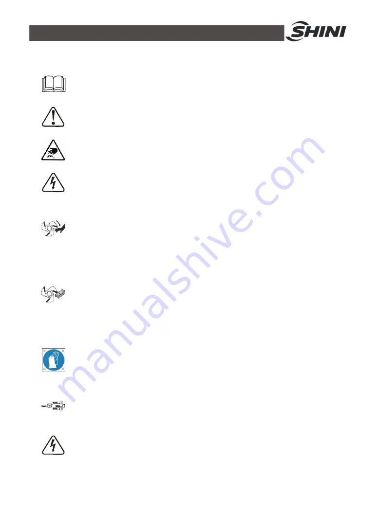
  Be careful! Not to be cut by the sharp blade. 


Power connection must be done by the professional electrician to avoid 

electrical shock. 


Caution! 

cutters should be laid level, prevent the cutters from self-rotating when 
do installation, don't let your hands be near to the cutters to avoid 
personal injury. 


Nnotice! 

Do not install the cutters by working together, because this could bring 
personal injury. Use a thick wood block to stop the rotating knives from 
turning. 


Notice! 

The blades are very sharp, so use protective gloves to avoid being cut. 


Notice!   

Please use new screws and gaskets when installing cutters. 

  The power connection of the granulator should be carried out by 

professional electrician so to avoid electrical shock! 


Summary of Contents for SG-3650E

Page 1: ...SG 36E Standard Central Granulators Date Apr 2013 Version Ver A English...

Page 2: ......

Page 3: ...General Description 17 2 1 1 Working Principle 17 2 2 Safety System 18 2 2 1 Emergency Stop 18 2 2 2 Safety Switch 18 2 2 3 Locking Screw 18 2 3 Assembly Drawing 20 2 3 1 Assembly Drawing 20 2 3 2 Pa...

Page 4: ...tallation of Blade Rest and Bearing 38 3 4 Installation of Belt Pulley and Motor 39 3 5 Installation of Fixed Blades and Rotating Blades 41 3 6 Installation of Regrind Storage Bin Screen and Screen Br...

Page 5: ...5 Monthly Check 55 6 6 6 Check Half yearly or Every 1000 Running Hours 56 6 6 7 3 year Checking 56 Form index Chart 1 1 Technical Specifications 12 Chart 2 1 Parts List 21 Chart 2 2 Cutting Chamber P...

Page 6: ...Picture 3 1 Installation Space 37 Picture 3 2 Installation Place 38 Picture 3 3 Installation of Blade Rest and Bearing 39 Picture 3 4 Installation of Belt Pulley and Motor 1 39 Picture 3 5 Installati...

Page 7: ...ture 4 1 Start Stop of the Machine 45 Picture 6 1 Remove the Fixed Blades 49 Picture 6 2 Daily Maintenance of V belt 51 Picture 6 3 Adjust the V belt 51 Picture 6 4 Bearing Coverv 52 Picture 6 5 Lock...

Page 8: ...8 56...

Page 9: ...flammable or toxic material SG 36E series of Standard central granulators are built to conform to sound proof models both in safety configuration and operation security They are suitable for centrali...

Page 10: ...red blades design can decentralize working load when granulating to increase cutting efficiency 4 Staggered blades retainer is designed for quick blades changing without re adjustment 5 Paddle blades...

Page 11: ...vice instructions intended for service engineers Other chapters contain instructions for the daily operator Any modifications of the machine must be approved by SHINI in order to avoid personal injury...

Page 12: ...Screen Meshes 10mm Level Detector Special Screens Dimensions H mm 1700 1700 H1 mm 1550 1550 W mm 1250 1500 W1 mm 500 750 D mm 1370 1425 Weight kg 1120 1360 Note 1 standard optional 2 For stainless ste...

Page 13: ...Labels Electrical installation must only be done by a competent electrician Before the granulator is opened for servicing and maintenance always disconnect the power with both the main switch and the...

Page 14: ...ed box Air inlet dust clean Attention No need for regular inspection because all the electrical parts in the control unit are fixed tightly 1 4 2 Transportation and Storage of the Machine Transportati...

Page 15: ...king environment The machine should be operated 1 Indoors in a dry environment with max temperature 45 and humidity no more than 80 Do not use the machine 1 If it is with a damaged cord 2 On a wet flo...

Page 16: ...ify the responsibilities and regulations born by any buyer or user who purchases products and accessories from Shini including employees and agents Shini is exempted from liability for any costs fees...

Page 17: ...ing Principle Parts name A Feed port B Rotating blades C Fixed blades D Screen E Storage bin Picture 2 1 Working Principle The plastic waste if feed via feed port A and falls down into the cutting cha...

Page 18: ...nce to the safety system of the granulator must be carried out by personnel with the necessary knowledge 2 2 1 Emergency Stop The granulator has an emergency stop button on the control panel and the e...

Page 19: ...he safety system of the granulator When it unscrewed the blades will be stopped To avoid personal injuries Picture 2 4 Locking Screw NOTE Do not change the screw length of locking screw Before turning...

Page 20: ...20 56 2 3 Assembly Drawing 2 3 1 Assembly Drawing Note Please refer to 2 3 2 material list about the parts code Picture 2 5 Assembly Drawing...

Page 21: ...i vibration case BH10364512810 BH10364512810 10 Anti vibration pad YW03162000000 YW03162000000 11 Pneumatic spring 1 YW01140000000 YW01160000000 12 Pneumatic spring 2 YW01090000000 YW01090000000 13 Pn...

Page 22: ...5 Right side plate of cutting chamber BW30367502010 1 BW30367502010 1 6 Inner hexagon cylindrical screw M10 45 YW61104500000 10 YW61104500000 10 7 Back block BW30365001110 1 BW30367514010 1 8 Fixed bl...

Page 23: ...part of bearing block BW30003600210 1 BW30003600210 1 5 Oil injection nozzle YW04010100000 2 YW04010100000 2 6 Seal ring BH13360100010 2 BH13360100010 2 7 Lower part of bearing block BW30003600410 1...

Page 24: ...st SG 3650E SG 3675E No Name Part No Quantity Part No Quantity 1 Taper sleeve YW30254800000 1 YW30254800000 1 2 Motor belt pulley YW30180400000 1 YW30180400000 1 3 Adjusting plate of motor 2 2 4 Motor...

Page 25: ...5365000220 1 BL55367502020 1 2 3 10 Screen Bracket Picture 2 10 Screen Bracket 2 3 11 Screen Bracket Parts List Chart 2 6 Screen Bracket Parts List SG 3650E SG 3675E No Name Part No Quantity Part No Q...

Page 26: ...List Chart 2 7 Feed Box and Cutting Chamber Parts List SG 3650E SG 3675E No Name Part No Quantity Part No Quantity 1 Feed port 1 1 2 Fender trim strip 1 1 1 3 Fender trim strip fixing plate 2 2 4 Fend...

Page 27: ...icture 2 12 Main Body 2 3 15 Main Body Parts List Chart 2 8 Main Body Parts List SG 3650E SG 3675E No Name Part No Quantity Part No Quantity 1 Rack 1 1 2 Right outshell 1 1 3 Electrical control box 1...

Page 28: ...28 56 2 4 Wiring Diagram 2 4 1 Main Circuit Picture 2 13 Main Circuit...

Page 29: ...29 56 2 4 2 Control Circuit Picture 2 14 Control Circuit 1...

Page 30: ...30 56 Picture 2 15 Control Circuit 2...

Page 31: ...31 56 2 4 3 Electrical Components Layout Picture 2 16 Electrical Components Layout...

Page 32: ...063500000 15 4 0mm 2 YE61040000000 16 4 0mm 2 PE YE61043500000 17 X2 Terminal 2 5mm 2 YE61250040000 18 2 5mm 2 YE61250040000 19 X2 Terminal 2 5mm 2 YE61250040000 20 S1 Emergency stop button 1NC YE1141...

Page 33: ...E61160000000 16 16mm 2 PE YE61163500000 17 6mm 2 YE61060000000 18 6mm 2 PE YE61063500000 19 X2 Terminal 2 5mm 2 YE61250040000 20 2 5mm 2 YE61250040000 21 X2 Terminal 2 5mm 2 YE61250040000 22 S1 Emerge...

Page 34: ...uxiliary contact terminals shown in 95 96 97 98 NC and NO contacts are shown in position 95 96 and 97 98 respectively 7 Main circuit connection No must correspond with terminal number of contactor At...

Page 35: ...20 BL55367503220 17 BL55365001520 BL55367503320 25 BL55365001620 BL55367503420 2 6 2 Blades International code Material China USA Japan SKD11 Cr12MoV D2 SKD11 2 6 3 Flywheel Picture 2 19 Flywheel Incr...

Page 36: ...self rotating when do installation don t let your hands be near to the cutters to avoid personal injury Nnotice Do not install the cutters by working together because this could bring personal injury...

Page 37: ...ble connection terminals should be tightened securely 5 The machine requires a 3 phase 4 wire power source connect the power lead L1 L2 L3 to the live wires and the earth PE to the ground 6 Power supp...

Page 38: ...g and lay it to be entrapped into the blade rest Use 120 degrees transfer oil to heat it up for 5 minutes 2 Fix the low half part of bearing base into both right and left sides of table board match th...

Page 39: ...lance of the driven wheel with dial gauge Stick the dial gauge to the driven wheel and rotate the driven wheel to see whether the value of the in dicator drops within 0 0 1 mm Picture 3 5 Installation...

Page 40: ...the middle If not adjust the driving wheel note NOT the driven wheel to make the driven wheel and driving wheel in balance Picture 3 7 Installation of Belt Pulley and Motor 4 8 Install the belt push...

Page 41: ...rew down the screws until the blade cannot sway anymore 3 Measure the space between the fixed blade and the rotating blade using a steel rule The normal space ranges is 0 4 0 5 mm If the space is not...

Page 42: ...closely with the very front fixing pothook 4 Put the storage bin underside of the grinding room 5 Fixed the safely switch Picture 3 10 Installation of Regrind Storage Bin Screen and Screen Bracket 3 7...

Page 43: ...eumatic spring fixing block to the lower left side of the Picture 3 13 Installation of Screen Screen Frame and Storage Bin 3 5 Install pneumatic spring and make its lower end link to the fixing pole o...

Page 44: ...estart Check 1 The unpainted parts of the machine are protected with oil prior to delivery and transport Clean the granulator from rust protection agent before it is used a Use dishcloth to clean firs...

Page 45: ...he motor d Restart and recheck 4 3 Start Stop of the Machine SG 36E series of granulator use the start and stop button located on the control panel for controlling Picture 4 1 Start Stop of the Machin...

Page 46: ...an cause personal injuries Clean the inside surface of the feed box before closing it 1 Check that the feed in case is empty and then start the machine 2 Loosen the lock screw of the feed box 3 Open t...

Page 47: ...k the overload relay of the motor The motor equiped with overload protector F1 in the electrical control box if the motor is overload the protector will trip off Trip blue button A eject out press Res...

Page 48: ...etween feed box and screen bracket is damaged daily 6 Check whether there is metal imputities in the cutting chamber before operation daily 7 Check whether all the safety swithes work normally daily 8...

Page 49: ...the blades are changed the blade fastening hexagon socket cap screws specification M16 70mm strength 12 9 and hardness HRC41 must be replaced by new ones 1 Remove the Fixed Blades Note In order to avo...

Page 50: ...ranulator is driven by four V belts 1 Check the V belt After 20 to 30 hours operation under full load check V belt tension and its working condition Check if the belt is wearing out every month 2 Chec...

Page 51: ...late on the control box that is located on the right side of the machine 2 Take out the storage bin loose the position adjusting screws of the motor 3 The tension of the belt could be altered by adjus...

Page 52: ...aintenance 1 Check if the plastic shutter at the intake of feeding hopper is broken or not If there is any damage replace it Or damaged parts may fall into cutting chamber and cause pollution It also...

Page 53: ...ned off before cleaning When you open the feeding hopper becareful not to touch the blades Sharp blades may cause personal injuries 1 Before turning off the machine please check if the material inlet...

Page 54: ...of the screen bracket and push into screen bracket 3 Fold down the screen bracket and install the screen to ensure to install the screen accurately via checking whether aligning the bulge and the holl...

Page 55: ...tch Check emergency stop button Check start stop button Check material check plate strip is perfect or not Check whether emergency stop and safety switch works normally Clean screen and feeding hooper...

Page 56: ...clamp ring of pulley is fastened Check belt tension 6 6 6 Check Half yearly or Every 1000 Running Hours Check or replace lubrication for gear motor Check lubrication of bearing Check coupling Evaluat...

Reviews: