15(65)
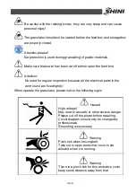
Warning
The cutter are very sharp, can cause injury
take out or open protective cover is not
allowed when it is running.
Keep some distance away from the cutters.
Notice
Read the instruction manual carefully before
operating.
Before start, do the safety devices test
according to the instruction. It is not allowed
to change the design of the machine unless it
is approved from the manufacturer.
1.4.2 Transportation and Storage of the Machine
Transportation
1) SG-24T series of granulator are packed in plywood cases with wooden pallet
at the bottom, suitable for quick positioning by fork lift.
2) After unpacked, castors equipped on the machine can be used for ease of
movement.
3) Do not rotate the machine and avoid collision with other objects during
transportation to prevent improper functioning.
4) The structure of the machine is well-balanced, although it should also be
handled with care when lifting the machine for fear of falling down.
5) The machine and its attached parts can be kept at a temperature from -25
℃
to +55
℃
for long distance transportation and for a short distance, it can be
transported with temperature under +70
℃
.
Storage
1) SG-24T series should be stored indoors with temperature kept from 5
℃
to 40
℃
and humidity below 80%.
2) Disconnect all power supply and turn off main switch and exigency stop
switch.
3) Keep the whole machine, especially the electrical components away from
water to avoid potential troubles caused by the water.
Summary of Contents for SG-24T
Page 1: ...SG 24T Screenless Granulator Date Apr 2013 Version Ver B English...
Page 2: ......
Page 8: ...8 65...
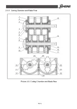
Page 25: ...25 65 2 3 3 Cutting Chamber and Blade Rest Picture 2 5 Cutting Chamber and Blade Rest...
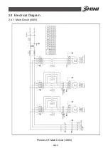
Page 29: ...29 65 2 4 Electrical Diagram 2 4 1 Main Circuit 400V Picture 2 9 Main Circuit 400V...
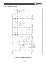
Page 30: ...30 65 2 4 2 Control Circuit 400V Picture 2 10 Control Circuit 400V...
Page 31: ...31 65 2 4 3 Electrical Components Layout 400V Picture 2 11 Electrical Components Layout 400V...
Page 34: ...34 65 2 4 5 Main Circuit 230V Picture 2 12 Main Circuit 230V...
Page 35: ...35 65 2 4 6 Control Circuit 230V Picture 2 13 Control Circuit 230V...
Page 36: ...36 65 2 4 7 Electrical Components Layout 230V Picture 2 14 Electrical Components Layout 230V...
Page 40: ...40 65 2 5 4 Proportional Valves Picture 2 18 Control Cabinet and Valve...


