45(65)
Picture 3-4: Installation of Bearing and Blade Rest 2
4) Fix the bearing base on the cutting chamber.
Picture 3-5: Installation of Bearing and Blade Rest 3
Daub the lubrication on the bearing and bearing base. Use proper
twisting force to lock the screw tightly.
3.4 Installation of Coupling and Motor
Notice!
To stop blade rest shaft rotating while installation, use a thick wood block
to stuck rotate blades!
1) Firstly fit coupling on cutter shaft to match key groove holes with the cutter
shaft key. At last, mount sensor and fasten it with inner hex bolt (M20x45).
Picture 3-6: Installation of Gear Motor 1
Summary of Contents for SG-24T
Page 1: ...SG 24T Screenless Granulator Date Apr 2013 Version Ver B English...
Page 2: ......
Page 8: ...8 65...
Page 25: ...25 65 2 3 3 Cutting Chamber and Blade Rest Picture 2 5 Cutting Chamber and Blade Rest...
Page 29: ...29 65 2 4 Electrical Diagram 2 4 1 Main Circuit 400V Picture 2 9 Main Circuit 400V...
Page 30: ...30 65 2 4 2 Control Circuit 400V Picture 2 10 Control Circuit 400V...
Page 31: ...31 65 2 4 3 Electrical Components Layout 400V Picture 2 11 Electrical Components Layout 400V...
Page 34: ...34 65 2 4 5 Main Circuit 230V Picture 2 12 Main Circuit 230V...
Page 35: ...35 65 2 4 6 Control Circuit 230V Picture 2 13 Control Circuit 230V...
Page 36: ...36 65 2 4 7 Electrical Components Layout 230V Picture 2 14 Electrical Components Layout 230V...
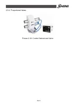
Page 40: ...40 65 2 5 4 Proportional Valves Picture 2 18 Control Cabinet and Valve...


