10(65)
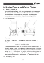
1.1 Coding Principle
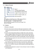
SG - xx xx x - xx
Shini Granulators
Length of Cutting Chamber (cm)
T=Double Cutting Chambers
(Only Applicable for SG-24 Series)
Width of Cutting Chamber (cm)
Option
*
Note
:
*
VR=Loading by High Pressure Air BR=Loading by Bolwer
BC=Blower Conveying & Cyclone Dust Collector
DS=Dust Separator H=Higher Motor Power
R=For Stainless Steel Made Feed Port and Storage Tank
CE=CE Conformity
1.2 Feature
1) Standard configuration
●
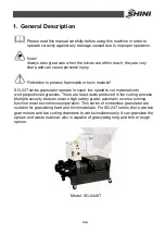
SG-24T series have two German-made gear motors and two cutting
chambers working simultaneously to provide reliable performance and high
torque.
●
SG-24T series feature integral design of double teeth cutters and cutting
blades. Staggered blades make the initial cutting and teeth cutters reduce
the materials into desired size. Regrinds could be used with virgin materials.
●
New-type inclined teeth cutter reduces the possibility of stress concentration,
enhance bearing capacity and converts force direction so that cutter lifespan
can be prolonged.
●
SG-24T series motor shaft and rotor shaft are connected by shaft coupling
thus ensuring smooth cutting action and convenient motor replacement.
●
When motor blockage occurs, the machine will alarm visibly and enable
motor fo run reversely. It resumes normal operation automatically after the
trouble is clear.
●
European type appearance, compact in size and easy to access for cleaning
and maintenance.
Summary of Contents for SG-24T
Page 1: ...SG 24T Screenless Granulator Date Apr 2013 Version Ver B English...
Page 2: ......
Page 8: ...8 65...
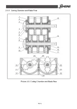
Page 25: ...25 65 2 3 3 Cutting Chamber and Blade Rest Picture 2 5 Cutting Chamber and Blade Rest...
Page 29: ...29 65 2 4 Electrical Diagram 2 4 1 Main Circuit 400V Picture 2 9 Main Circuit 400V...
Page 30: ...30 65 2 4 2 Control Circuit 400V Picture 2 10 Control Circuit 400V...
Page 31: ...31 65 2 4 3 Electrical Components Layout 400V Picture 2 11 Electrical Components Layout 400V...
Page 34: ...34 65 2 4 5 Main Circuit 230V Picture 2 12 Main Circuit 230V...
Page 35: ...35 65 2 4 6 Control Circuit 230V Picture 2 13 Control Circuit 230V...
Page 36: ...36 65 2 4 7 Electrical Components Layout 230V Picture 2 14 Electrical Components Layout 230V...
Page 40: ...40 65 2 5 4 Proportional Valves Picture 2 18 Control Cabinet and Valve...


