background image


62(65) 


1) Check the power wire to see whether there is any damage. If so, replace it 

immediately. 

2) Check the safety switch. 

3) Check whether there is looseness in electrical connections.   

6.3.3    Monthly Check 

1) Check whether coupling is damaged or not. 
2) Check whether blades are loose or abraded. 

6.4  Cleaning 


Caution: The blade may do harm to human body when opening the feed 
box! 

1) Check whether the feed box is emptied before stopping the machine. 
2) Clean the exterior surface of the feed box. 
3) Turn off the main power switch. 
4) Clean the shutter of the feed box with a dust separator. 
5) Unscrew the star knob to open the feed box backward.     
6) Clean the interior surface of the feed box. 
7) Unscrew star screw and take out storage bin.     
8) Clean storage bin. 
9) Clean both surfaces of the cutting chamber; open the upper cutting chamber 

and to clean the remained material by using revolving rod to turn the blade 
shaft. 

10) Clean the belt pulleys with bright dust-precipitator. 

Summary of Contents for SG-24T

Page 1: ...SG 24T Screenless Granulator Date Apr 2013 Version Ver B English...

Page 2: ......

Page 3: ...Principle 18 2 2 Safety System 18 2 2 1 Emergency Stop 19 2 2 2 Safety Switch 20 2 2 3 Gate Lock 20 2 3 Assembly Drawing 21 2 3 1 System Structure SG 24T 21 2 3 2 Parts List SG 24T 22 2 3 3 Cutting Ch...

Page 4: ...4 3 4 Installation of Coupling and Motor 45 3 5 Installation of Rotating Blade and Fixed Blade 46 3 6 Installation of Feed Box Feed Port and Storage Bin 48 4 Operation Guide 50 4 1 Startup Pretest 50...

Page 5: ...Check 64 6 5 6 Check Half yearly or Every 1000 Running Hours 65 6 5 7 3 year Checking 65 Table index Table 1 1 Technical Specifications 12 Table 2 1 Parts List SG 2427T 22 Table 2 2 Parts List SG 2436...

Page 6: ...39 Picture 2 17 Full recevier Alarm Devices 39 Picture 2 18 Control Cabinet and Valve 40 Picture 3 1 Installation Notice 42 Picture 3 2 Installation Place 44 Picture 3 3 Installation of Bearing and B...

Page 7: ...START Emergency Stop and STOP Button 53 Picture 4 4 Motor Reversed Protection 54 Picture 6 1 Blades Maintenance 58 Picture 6 2 Dismantle Fixed Blades 59 Picture 6 3 Dismantle Rotate Blades 59 Picture...

Page 8: ...8 65...

Page 9: ...r operate in super low speed to cut materials into well proportioned granules There are least dusts produced in the cutting process Multiple security devices ensure high safety grade automatic reverse...

Page 10: ...ries feature integral design of double teeth cutters and cutting blades Staggered blades make the initial cutting and teeth cutters reduce the materials into desired size Regrinds could be used with v...

Page 11: ...ling and servicing Chapter 6 which contains service instructions intended for service engineers Other chapters contain instructions for the daily operator Any modifications of the machine must be appr...

Page 12: ...ng Regrind Conveyor BC Type Dust Separator Level Detector Proportional Valve Manual Storage Bin Dimensions H mm 1360 1360 1360 H1 mm 1060 1060 1060 W mm 773 773 773 W1 mm 620 620 620 D mm 1160 1269 13...

Page 13: ...Labels Electrical installation must only be done by a competent electrician Before the granulator is opened for servicing and maintenance always disconnect the power with both the main switch and the...

Page 14: ...need for regular inspection because all the electrical parts in the control unit are fixed tightly When operate the granulator please notice the following signs Hazard High voltage May lead to casualt...

Page 15: ...equipped on the machine can be used for ease of movement 3 Do not rotate the machine and avoid collision with other objects during transportation to prevent improper functioning 4 The structure of the...

Page 16: ...over 3000m 5 At least 1m surrounding space is requested when this equipment is running Keep this equipment away from flammable sources at least two meters 6 In the work area of vibration and strong ma...

Page 17: ...d from liability for any costs fees claims and losses caused by reasons below 1 Any careless or man made installations operation and maintenances upon machines without referring to the Manual prior to...

Page 18: ...me A Feed box B Teeth cutter C Staggered blade D Motor E Fixed blade F Storage bin Picture 2 1 Working Principle The material is fed in via a feed box A and falls down to the teeth cutters B the block...

Page 19: ...dangerous condition and subject to accident happening The maintenance and preservation of safety system shall be done by professional staff In case the safety system of granulator is changed our compa...

Page 20: ...one is located between the feed box and the cutting chamber while the other one is between the storage bin and machine body 2 2 3 Gate Lock For opening feed box and cutting chamber users need to loose...

Page 21: ...21 65 2 3 Assembly Drawing 2 3 1 System Structure SG 24T Note Please refer to 2 3 2 material list about the parts code Picture 2 4 System Structure SG 24T...

Page 22: ...eft case block at bottom BH10242702310 47 Right shaft sleeve BW30002400110 18 Cutting chamber turning block 2 BH10240900210 48 Mid case block at bottom BH11300000720 19 Left case block at top BW302427...

Page 23: ...at bottom BH10243602310 47 Right shaft sleeve BW30002400110 18 Cutting chamber turning block 2 BH10240900210 48 Mid case block at bottom BH10243604210 19 Left case block at top BW30240680010 49 Middl...

Page 24: ...ock at bottom BH10244602310 47 Right shaft sleeve BW30002400110 18 Cutting chamber turning block 2 BH10240900210 48 Mid case block at bottom BH10244601510 19 Left case block at top BW30244600310 49 Mi...

Page 25: ...25 65 2 3 3 Cutting Chamber and Blade Rest Picture 2 5 Cutting Chamber and Blade Rest...

Page 26: ...ip 4 4 4 7 Bearing 4 4 4 8 Right shaft sleeve 2 2 2 9 Shaft 2 2 2 10 Mid Staggered blade T 2 2 2 11 Back bearing holder at bottom 1 1 1 12 Rear bearing seat 2 2 2 13 Left shaft sleeve 2 2 2 14 Middle...

Page 27: ...Picture 2 6 Transmission 2 3 5 1 Transmission Parts List Table 2 5 Transmission Parts List Quantity Name Name SG 2427T SG 2436T SG 2446T 1 Reduction gear 2 2 2 2 Coupling 2 2 2 3 Inductive wheel 2 2 2...

Page 28: ...List Table 2 6 Feed Box Feed Port and Material Stopper Parts List Quantity Name Name SG 2427T SG 2436T SG 2446T 1 Feed box 1 1 1 2 Material stopper 1 1 1 3 Feed port 1 1 1 4 Handle 1 1 1 2 3 8 Storag...

Page 29: ...29 65 2 4 Electrical Diagram 2 4 1 Main Circuit 400V Picture 2 9 Main Circuit 400V...

Page 30: ...30 65 2 4 2 Control Circuit 400V Picture 2 10 Control Circuit 400V...

Page 31: ...31 65 2 4 3 Electrical Components Layout 400V Picture 2 11 Electrical Components Layout 400V...

Page 32: ...ard 32A YE61250040000 15 YE61253500000 16 Terminal board 32A YE61250040000 17 YE61253500000 18 Terminal board 32A YE61250040000 19 X10 Metal tie in 250V 4P YE68025400000 YE68025400100 20 S1 Emergency...

Page 33: ...40000 15 YE61253500000 16 Terminal board 32A YE61250040000 17 YE61253500000 18 Terminal board 32A YE61250040000 19 X10 Metal tie in 250V 4P YE68025400000 YE68025400100 20 S1 Emergency stop 400V 10A YE...

Page 34: ...34 65 2 4 5 Main Circuit 230V Picture 2 12 Main Circuit 230V...

Page 35: ...35 65 2 4 6 Control Circuit 230V Picture 2 13 Control Circuit 230V...

Page 36: ...36 65 2 4 7 Electrical Components Layout 230V Picture 2 14 Electrical Components Layout 230V...

Page 37: ...nal board 32A YE61250040000 13 YE61253500000 14 X10 Metal tie in 250V 4P YE68025400000 15 250V 4P YE68025400100 16 S1 Emergency stop 400V 10A YE11320300000 17 S2 STOP button 400V 10A YE11375800000 18...

Page 38: ...E61250040000 13 YE61253500000 14 X10 Metal tie in 250V 4P YE68025400000 15 250V 4P YE68025400100 16 S1 Emergency stop 400V 10A YE11320300000 17 S2 STOP button 400V 10A YE11375800000 18 S3 H1 STARTP bu...

Page 39: ...2 5 1 30 second Instant Recycling System Picture 2 15 30 second Instant Recycling System 2 5 2 Storage Bin Picture 2 16 Storage Bin 2 5 3 Full recevier Alarm Devices Level Motor Picture 2 17 Full rece...

Page 40: ...40 65 2 5 4 Proportional Valves Picture 2 18 Control Cabinet and Valve...

Page 41: ...uries Power supply of the machine should be handled by qualified electricians Be careful Cutting blades must be put balanced prevent it to rotate itself when do the installation Keep hands from blades...

Page 42: ...N OFF switch The cable s dia Should not smaller than those applied in the control box 4 The power cable connection terminals should be tightened securely 5 The machine requires a 3 phase 4 wire power...

Page 43: ...610 710 M22 146000 208000 244000 580 820 960 M24 168000 240000 281000 730 1050 1220 M27 222000 316000 369000 1100 1550 1800 Coarse thread M30 269000 384000 449000 1450 2100 2450 M8 1 18100 26600 31200...

Page 44: ...ng and Blade Rest 1 Install the bearing 2 bearing washer 1 bearing sleeve 7 into the bearing base 3 2 Insert the blade shaft4into the bearing sleeve vertically 7 Then sleeve the staggered blade 5 and...

Page 45: ...ring base Use proper twisting force to lock the screw tightly 3 4 Installation of Coupling and Motor Notice To stop blade rest shaft rotating while installation use a thick wood block to stuck rotate...

Page 46: ...ng mount and installation use a thick wood block to stuck rotate blades Caution The cutting blade rest shall be put stably and avoid cutter self rotation At the time of operating hand shall stay away...

Page 47: ...hem up with right torque M12x25 5 After installed the rotating blade rest to the housing mount fixed blades that correspond with teeth cutters on pressing block and align their holes Lockup the fixing...

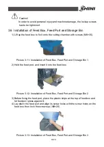
Page 48: ...on of Feed Box Feed Port and Storage Bin 1 2 Hold the feed port and insert it into the feed box Picture 3 12 Installation of Feed Box Feed Port and Storage Bin 2 3 Before fixing the feed port place th...

Page 49: ...49 65 5 Hold the storage bin with both hands and push it into its right position along the slide way 6 Lock up plum blossom handle...

Page 50: ...t oil should be cleaned 1 Clean with a towel 2 Wash with a towel dipping with amyl acetate 4 1 1 Before the First Startup 1 Check whether the granulator is in the level state 2 Check the space of the...

Page 51: ...ssing the STOP button 6 The granulator needs some time to fully come to a halt after full stop check whether the running direction is clockwise The cutting tools may be damaged and the granulating cap...

Page 52: ...ure feed box is fully closed otherwise machine would not start 1 Check to ensure there is no powder left in the interface or corners 2 Close the feed box forwardly 3 Lock up the star screw and fix the...

Page 53: ...emergency stop button Main power switch is located at the front control panel And the startup and stop of the machine is controlled through rotating the main poewer switch Picture 4 2 Main Power Swit...

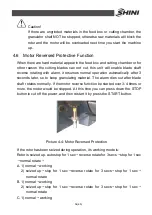
Page 54: ...ter so to keep granulating material The alarm dies out after blade shaft rotates normally If the motor reverse function be started over 3 4 times or more the motor would be stopped At this time you ca...

Page 55: ...55 65 2 seized up machine stops Notice Mount sensor and ensure its space with big wheel to about 2 4mm...

Page 56: ...r overloads Under that situation A the green pole will sprout Press the Reset button B to reset it Before startup again check whether there is any material in the granulator 4 Check the space between...

Page 57: ...professionals to avoid damage to machine and harm to human body 6 1 1 Replace the Blades Caution Self rotation exists due to non balanced forces Caution Self rotation also happens when barycenter is u...

Page 58: ...lity of harm to other people the replacement action must be conducted by oneself To avoid self rotation block the rotating blades with a thick wood block Be careful with the sharp blades Each time to...

Page 59: ...des Caution Press the pressing block and blade when you remove the last screw so to avoid personal injuries 3 Install the blades Clean carefully the fixed blades and rotating blades and then install t...

Page 60: ...it as soon as possible d Check the lubricating oil level and install oil level plug 3 Lubricating oil replacement Increased viscosity of the lubricating oil will make it harder to discharge the oil s...

Page 61: ...tting chamber 2 Check whether the Emergency Stop works properly Start the machine and then stop it via Emergency Stop Rotate the button anti clockwise to reset the Emergency Stop 3 Check the main powe...

Page 62: ...k whether the feed box is emptied before stopping the machine 2 Clean the exterior surface of the feed box 3 Turn off the main power switch 4 Clean the shutter of the feed box with a dust separator 5...

Page 63: ...63 65 Picture 6 5 Machine Cleaning Notice Finish step 9 for every time of machine cleaning and also it at least has to be done for one time after 300 hours in operation...

Page 64: ...ck emergency stop button Check start stop button Check material check plate strip is perfect or not Check whether emergency stop and safety switch works normally Clean screen and feeding hooper Check...

Page 65: ...clamp ring of pulley is fastened Check belt tension 6 5 6 Check Half yearly or Every 1000 Running Hours Check or replace lubrication for gear motor Check lubrication of bearing Check coupling Evaluat...

Reviews: