47(65)
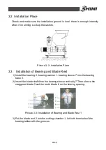
Picture 3-8: Installation of Rotating Blade and Fixed Blade 1
3) Put the rotating blade rest at the bottom block of the cutting chamber and
align its holes with the holes on cutting chamber.
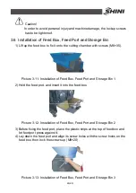
Picture 3-9: Installation of Rotating Blade and Fixed Blade 2
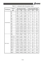
4) Use a wrench to tight up all the screws on bearing block or cutting chamber
and lock them up with right torque (M12x25).
5) After installed the rotating blade rest to the housing, mount fixed blades that
correspond with teeth cutters on pressing block and align their holes. Lockup
the fixing screw (LOCTITE243 thread fixing glue is recommended). (Fixing
screw for front fixed blade is M10x30, while for back fixed blade is M10x35).
Picture 3-10: Installation of Rotating Blade and Fixed Blade 3
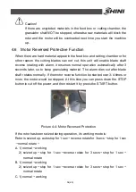
Caution!
Gap between rotate and fixed blades is unadjustable. Please rotate
therest after installation to check blade rest in oreder to avoid damage.
Summary of Contents for SG-24T
Page 1: ...SG 24T Screenless Granulator Date Apr 2013 Version Ver B English...
Page 2: ......
Page 8: ...8 65...
Page 25: ...25 65 2 3 3 Cutting Chamber and Blade Rest Picture 2 5 Cutting Chamber and Blade Rest...
Page 29: ...29 65 2 4 Electrical Diagram 2 4 1 Main Circuit 400V Picture 2 9 Main Circuit 400V...
Page 30: ...30 65 2 4 2 Control Circuit 400V Picture 2 10 Control Circuit 400V...
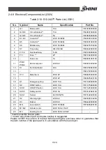
Page 31: ...31 65 2 4 3 Electrical Components Layout 400V Picture 2 11 Electrical Components Layout 400V...
Page 34: ...34 65 2 4 5 Main Circuit 230V Picture 2 12 Main Circuit 230V...
Page 35: ...35 65 2 4 6 Control Circuit 230V Picture 2 13 Control Circuit 230V...
Page 36: ...36 65 2 4 7 Electrical Components Layout 230V Picture 2 14 Electrical Components Layout 230V...
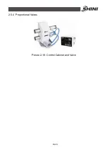
Page 40: ...40 65 2 5 4 Proportional Valves Picture 2 18 Control Cabinet and Valve...


