PN-L803C/80TC3 SERVICE MENU/VARIOUS SETTING TOOL OPERATING PROCEDURES 4- 37
19. FLICKER ADJUSTMENT TOOL
■
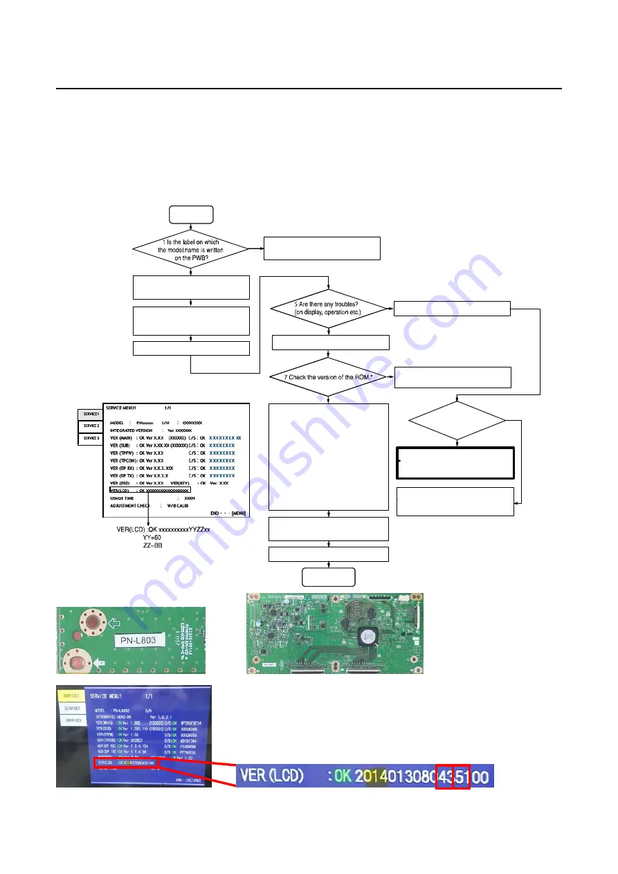
Outline
The LCD flicker adjustment is performed after replacing the C-PWB and the LCD module.
■
Instrument
-
PC for adjustment
The PC needs to have LAN port :100BASE TX/10BASE TX.
-
Screwdriver
Used for opening/closing of rear cabinet.
■
Flow chart
Start
4
Turn on IDP.
8
Adjust with service tool.
10
Remove the LAN cable
End
Yes
No
Yes
No
2
Confirm that main power SW is off.
3
Connect the PC and IDP with LAN
cable.
9
Turn off IDP.
Turn off right away
Checking harness
connections is done?
Cause of inferiority is not T-CON PWB
OR
This T-CON PWB has some defects.
Confirm the connection of FFC and
LVDS, and turn on again and retry
adjustment.
-
Refer to "19 - 1. OPERATING
CONDITIONS FORTHE
FLICKER ADJUSTMENT
TOOL".
-
Refer to page "19 - 2
. BOOTING
PROCEDURES OFTHE
FLICKER ADJUSTMENT
TOOL".
-
Refer to page "19 - 3
. FLICKER
ADJUSTMENT P
ROCEDURES".
T-CON PWB is not appropriate
Please use another T-CON PWB.
No
6 To enter the service menu
Version of the ROM is not appropriate.
Please use another T-CON PWB.
*Check the version of the ROM.
Summary of Contents for PN-80TC3
Page 183: ...PN L803C 80TC3 TROUBLESHOOTING 7 10 FUSE POSITION MAIN PWB F2200 F2300 F2102 F2302 F2101 ...
Page 184: ...PN L803C 80TC3 TROUBLESHOOTING 7 11 5V POWER SUPPLY PWB F2100 F2100 ...
Page 191: ...PN L803C 80TC3 HARDWARE DESCRIPTIONS 8 7 3 BLOCK DIAGRAM Block diagram ...
Page 202: ...PN L803C 80TC3 HARDWARE DESCRIPTIONS 8 18 5 PARTS LAYOUT Main PWB TOP ...
Page 203: ...PN L803C 80TC3 HARDWARE DESCRIPTIONS 8 19 BOTTOM ...
Page 204: ...PN L803C 80TC3 HARDWARE DESCRIPTIONS 8 20 LED Power Supply PWB TOP ...
Page 205: ...PN L803C 80TC3 HARDWARE DESCRIPTIONS 8 21 BOTTOM ...
Page 206: ...PN L803C 80TC3 HARDWARE DESCRIPTIONS 8 22 Key PWB TOP BOTTOM ...


