4
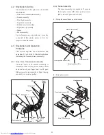
Motor assembly
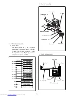
Dot pulse sensor (DP)
Home position sensor (HP)
Main PCB assembly
Carriage
Head assembly
Reset pulse sensor (RP)
Main PCB assembly
2-2 Mechanism Outline
The mechanism of this printer can be divided
into 9 blocks.
• Drive force transmission assembly
• Sensor assembly
• Print head assembly
• Paper feed assembly
• Ribbon cassette assembly
• Paper take-up assembly
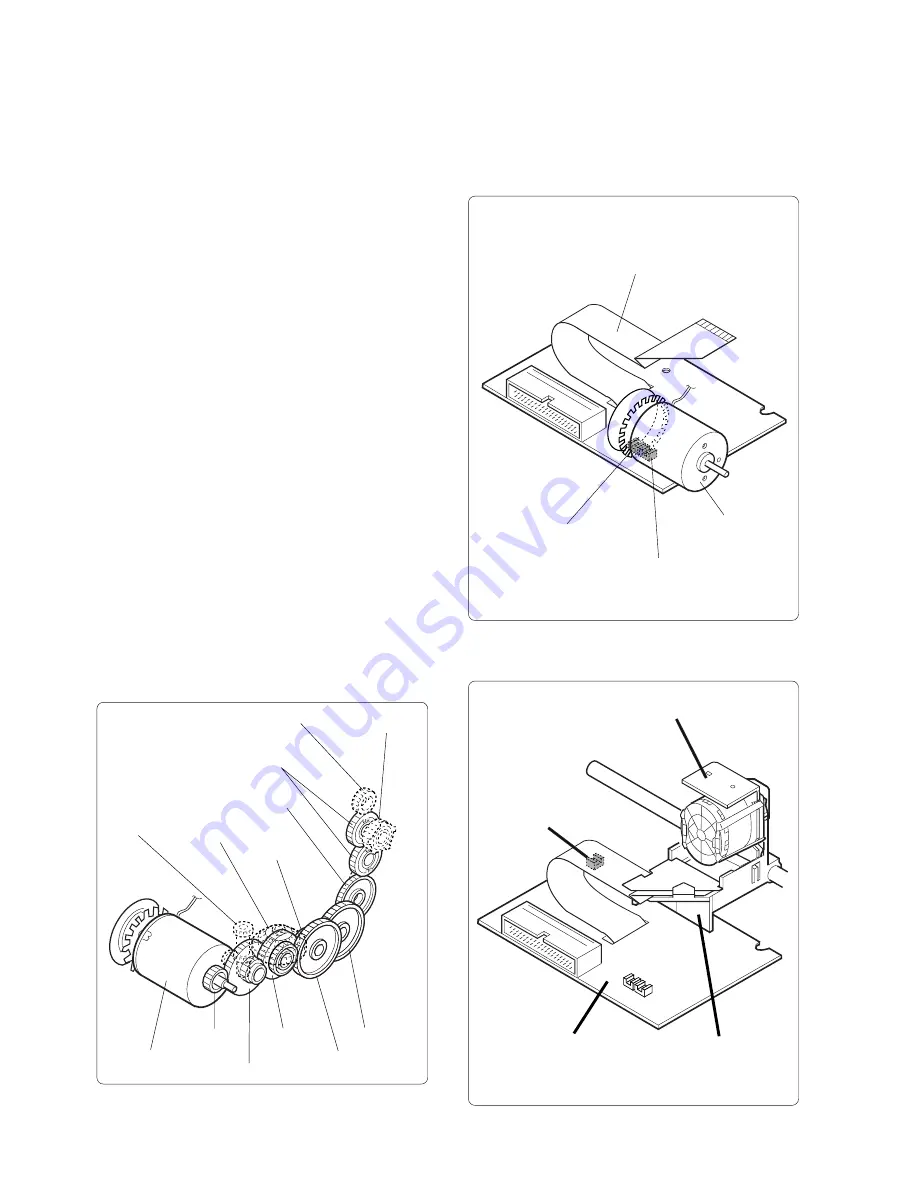
Motor assembly
Motor gear
Reduction gear 1
Reduction
gear 2
Reduction
gear 3
Reduction
gear 4
PF gear
Winder
pulley
Idling gear 2
Idling gear 1
Bevel gear 2
Bevel gear 1
Worm wheel
• Frame
• Motor assembly
For information on peripheral circuitry
connected to this printer, please refer to the
respective documentation.
2-3 Mechanism and Operation
Principles
This section explains the construction and
operation of 8 out of the 10 blocks listed above
(excluding the frame and motor assembly).
2-3-1 Drive Force Transmission Assembly
The drive force of the motor assembly is
transmitted to the various parts as follows. Print
head via bevel gear, Paper feed, via PF gear,
Ribbon cassette via worm wheel, Paper take-up
assembly via winder pulley.
2-3-2 Sensor Assembly
The sensor assembly is comprised of 3 sensors;
the dot pulse sensor (DP), home position sensor
(HP) and reset pulse sensor (RP).
(1) Dot pulse sensor/home position sensor
(2) Reset pulse sensor


