30
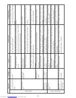
Motor does not
move.
Motor normal
Carriage operation
normal
Check points
Countermeasure
Remove carriage and check engaging condition of
carriage drive pin and pulley.
Check whether carriage rails (front and back) are
lubricated.
Measure voltage between pins 29 (+) and 24 (-) of
connector on main PCB assembly and verify that 5 V DC
is supplied.
Observe waveform of signal at pin 6 (HP), pin 8 (DP),
and pin 26 (RP) and check whether signal is normal.
Check circuit hardware of printer control section and
connection cable to printer.
Check FFC connection condition.
Check whether replacing print head assembly solves the
problem.
Note that if the printer control section is defective, the
head can be destroyed.
Verify that ribbon cassette is loaded correctly.
Measure voltage between pins 29 (+) and 24 (-) of
connector on main PCB assembly and verify that 5 V DC
is supplied.
Observe waveform of signal at pin 6 (HP), pin 8 (DP),
and pin 26 (RP) and check whether signal is normal.
If there is a phase shift, reseat the time
belt assembly.
Lubricate if not sufficiently
lubricated.
If not supplied, repair the printer control
section.
If signal is not normal, replace the main
PCB assembly.
If there is a problem, repair the printer
control section or replace the connecting
cable.
Reinsert FFC if disconnected.
If operation is normal, replace the print
head assembly.
If not correct, reinsert.
If not supplied, repair the printer control
section.
If signal is not normal, replace the main
PCB assembly.
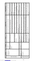
Symptom
Condition
Cause
Carriage does not
move.
Carriage does not
stop.
Unit does not print
(all dots/specific
dots).
Timing belt assembly and
pulley phase shift
Carriage actuator problem
DP/HP/RP signal problem
Control section problem
Head FFC disconnected
Print head assembly
is defective
Ribbon cassette not
inserted properly
DP/HP/RP signal problem
Head movement problem
Print problem

