


Processor setup
Page 66
FP400 Product Guide
Processor setup
Processor setup requires configuring the inputs and outputs (I/O) and for network based
processors, specifying the network configuration.
Specify the Auxiliary I/O control mode
There are 2 methods of operation for the processor’s inputs and outputs, Local control and
Remote control. When set to Local control mode, the processor uses its relays to signal alarm and
supervision conditions, and the inputs are used to activate electronic self-tests. For network based
processors set to Remote control mode, alarm data is carried over the network cables and the six
relays are available as output control points from the security management system. In Remote
control mode the inputs are used to report the status of one, or two, auxiliary security devices to
the host SMS. This section details the procedures for configuring the processor’s I/O for Local
control and Remote control operation.
1.
On the Aux Cfig tab select the Arrow beside the Aux Control: field.
2.
Specify the control mode for this processor (Local or Remote).
3.
Select the Download button to save the configuration changes to the processor.
Auxiliary (Aux) inputs
The two Aux inputs on the FP400 processor are voltage sensing inputs. The processor determines
an input’s status via an internal reference voltage, and the configuration of the contact closures
and supervision resistors. Input contact closures MUST be voltage-free. You define the inputs as
normally open (NO) or normally closed (NC) with single resistor supervision, dual resistor
supervision, or unsupervised. The Filter Window parameter allows you to set the time period for
which an input must be active, before the processor reports an event.
Local control mode
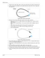
In local control mode, the two Aux inputs initiate processor self-tests. To activate the self-test
function, close a momentary switch across an input. The switch must close for the time specified in
the Filter Window. Leave the AUX inputs open if you do not want to use the self-test function.
shows the input wiring configuration for a self-test switch (unsupervised N.O.).
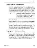
Remote control mode
In Remote control mode, the two Aux inputs serve as auxiliary device inputs to the host computer.
The inputs are available for reporting the status of other security devices. The processor reports
any change of an input’s state to the head end system.
includes the selectable Remote
Control input wiring configurations and
lists the selectable supervision resistor values.