


Installing the FP400 processor
Page 40
FP400 Product Guide
Figure 39 1 RU rack-mount shelf (p/n F4MD0500)
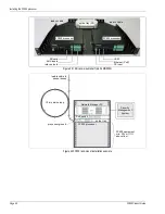
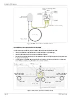
Figure 40 FP400 rack-mount installation example
FP400 processor
Ethernet (PoE)
AUX inputs
splice tray (X2)
lead-in cable
relay outputs
UCM
SD card
DC input
lead-in cable
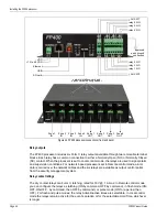
FP400 processor
splice tray
Network Manager PC
FP400 processor
lead-in cable to
10 m service loop
PoE switch
sensor zones
Security
Management
System
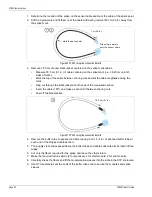
FP400 equipment
min. 30 cm (1 ft.)
above floor
processor ground