


FP400 components
Page 10
FP400 Product Guide
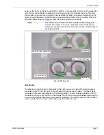
LED indicators
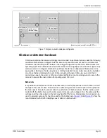
The processor includes 10 LED indicators to visually display its current status.
front and rear panel LEDs and
provides the display state details.
Network communications
The FP400 processor includes an Ethernet port for network communications and power (PoE).
Alternatively, a network interface card (NIC) can be plugged into the processor to enable Silver
Network communications via EIA-422 copper wire, or fiber optic cable. Network communications
are managed by the Silver Network Manager (NM) and communication to a third-party SMS can
be made via the Network Manager Interface.
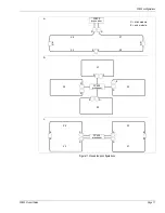
Zone kit
The zone kit (p/n F4KT0200) includes a start module, an end module, 10 splice sleeves, and
labels for the SC/APC connections to the processor. For each sensor zone, 2 SC/APC connectors
with 1 m (3.3 ft.) fiber leads are harvested from the start module. The 2 connectors are spliced to 2
fibers in the lead-in cable for the connection between the processor and the lead-in cable. The
SC/APC connectors are labeled to ensure they are connected to the appropriate TX and RX ports
on the processor. The non-detecting lead-in cable runs between the processor and the start
module located at the beginning of the sensor zone. At the start point of the zone, the two fibers in
the lead-in cable are spliced to one side of the start module. The two fibers on the other side of the
start module are spliced to two fibers in the detecting section of sensor cable. The detection zone
Figure 3 FP400 LED indicators
LED Name
LED OFF
LED Green
LED Red
LED Amber
PWR (2)
power OFF
power ON
power fault
N/A
LASER
Laser OFF
Laser ON
Laser fault
N/A
SD
no SD card
card in (steady) / writing (blinks)
SD card fault N/A
COM A
no activity side A
A side receive (blinks)
A side fault
N/A
COM B
no activity side B
B side receive (blinks)
B side fault
N/A
ZONE 1
disabled
enabled and secure
zone alarm
supervision
ZONE 2
disabled
enabled and secure
zone alarm
supervision
ZONE 3
disabled
enabled and secure
zone alarm
supervision
ZONE 4
disabled
enabled and secure
zone alarm
supervision
Table 1 LED indications
Note
Network communications can use either the onboard Ethernet, or an
optional NIC, not both.
Note
Each sensor zone requires one, or two, splice enclosures. Splice
enclosures are ordered separately.
front panel LEDs
rear panel LEDs