


FP400 initial calibration
Page 62
FP400 Product Guide
FP400 calibration is a five step process that involves:
•
Adjusting the processor’s RX Cable gain settings (if required)
•
Tuning the processor’s detection settings (if required)
•
Adjusting the processor’s supervision settings (if required)
•
Adjusting the processor’s Filter settings (if required)
•
Testing the installation
Connecting the UCM via USB
1.
Connect the UCM computer to the processor via USB (to the UCM port).
2.
Start the UCM software (the UCM Connect dialog displays).
3.
Select Connect to establish a connection to the processor.
(e.g., Network Type: = Silver Network; Device Type = FP400; Address = 1 {default address};
select the USB radio button; USB Device = fp400). The FP400 Status window opens:
Note
The processor’s Address and Network Configuration settings can be
adjusted only through a direct USB connection.
Note
The FP400 processor must be powered by either PoE or a direct DC
input (12 - 48 VDC) to connect to the UCM.
Note
For FP400 systems that encounter an unacceptable NAR during
inclement weather, raise the Event Threshold to reduce the NAR.
After adjusting the Event Threshold, retest the system to ensure that
the detection meets the site’s security requirements.
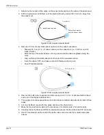
Figure 69 UCM Status screen
details about the connected processor
change the processor’s network Address
update the processor’s firmware
Event Log
Diagnostic Status field
sensor Zone Status
I/O status
History button
Maximum and Minimum signal levels