


FP400 Product Guide
Page 21
3
Installing the FP400
FP400 installation overview
There are ten steps to completing an FP400 installation:
1.
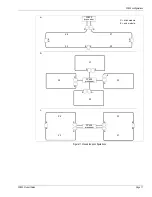
Create a detailed site plan.
2.
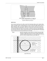
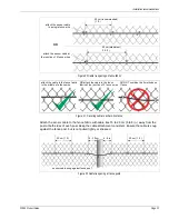
Deploy the sensor cable alongside the fence according to the site plan.
3.
Attach the sensor cable to the fence.
Pull the cable through bypass conduit, if required.
Attach cable to protected gates, if required.
4.
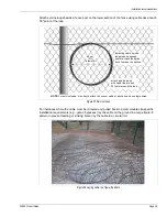
Make the fusion splices.
5.
Create splice point service loops, and attach the loops to the fence.
6.
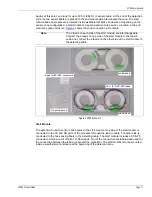
Use a visual fault locater (VFL) to verify the continuity of each spliced fiber (recommended).
7.
Install and connect the FP400 processor.
8.
Setup and configure the system software.
9.
Calibrate the sensor.
10. Test the system to ensure it meets the site’s detection requirements.
Laser light safety
CAUTION
Fusion splicing the sensor cable must be done by qualified personnel
who are trained and certified in fiber optic cable installation to telecom
industry standards.
Dispensing the sensor cable and attaching the cable to the fence requires
minimal training.
WARNING
The FP400 processor contains a Class I laser light source.
NEVER look directly into the end of a fiber connector.
Ensure that the fiber optic light source is off, BEFORE using a scope to
check a fiber optic connector.