


Program the
Account number
. This account number will be used for all reporting events. Use
the
[#] key to enter
additional hex symbols:
B
,
C
,
D
,
E
,
F
.
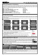
SERIAL Interface
2
Account number
1234
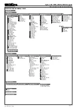
Short programming manual - basic information
Intruder alarm system
System with
KM24, KM24A
, KM24G keypads
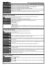
SERIAL INTERFACE SETTINGS
GPRS SETTINGS
The
SERIAL interface
menu is used to enable reporting to the device which is connected to
the
SERIAL port.
The
GPRS settings
menu contains parameters that enable the routing of specified events for up to two CMS receivers via GPRS.
Service Mode
}
Report settings
}
SERIAL Interface
Service Mode
}
Report settings
}
GPRS settings
This menu allows to enable /disable reporting to the device which is connected to
the
SERIAL port. Control panel
uses protocol
7 byte slow
by default
.
Use software MASCAD to change the protocol to
9600 Baud Serial
.
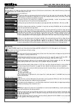
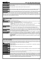
All settings below are visible when reporting to CMS Receiver No.1 or Receiver No.2 via GPRS is enabled.
Use GPRS as backup
- if communication with a receiver is not established via PSTN or LAN, the system
sends a report via GPRS.
Address
- program the address of the CMS receiver (for example: 77.201.45.26 or receiver.secolink.eu).
Use the [1] key to enter the DOT character for the address.
Port -
program the port used for communication with
the
CMS receiver.
Account number
- this account number will be used for all reporting events. Use
the
[#] key to enter additional
hex symbols:
B
,
C
,
D
,
E
,
F
.
Note:
this account number is also used
in the SERIAL interface menu
.
Protocol
- define the protocol format used to report system events. Available protocols:
E2
,
CSV IP,
Fibro
.
Transport
- define transport layer protocol:
TCP
or
UDP.
Use as backup for Rec.1
- if communication with a receiver No.1 is not established via GPRS, the system
sends
the
report to a receiver No.2
Use same Acc. as Rec.1
- use
the
same account set for the receiver No.1.
SERIAL Interface
Reporting
Enabled
1
GPRS settings
GPRS settings
Receiver No.1
Receiver No.2
Enabled
Enabled
1
2
Address
Use same Acc. as Rec.1
Use GPRS as backup
Use as backup for Rec.1
Port
Account number
Protocol
Transport
77.201.45.26
No
Yes
Yes
9999
1234
E2
TCP
3
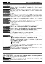
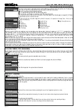
GPRS settings
banga
User name
APN
Password
APN
is the name of a gateway between a GPRS mobile network and another computer network, frequently the
public Internet. A GSM/GPRS module making a data connection must be configured with an APN to present to
the network provider. Contact your provider to verify the correct APN settings.
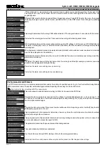
4
GPRS settings
Yes
Send every
15 sec
Periodic test
The
Periodic test
menu enables you to set the time period that the module will automatically send a test report to
the CMS in order to check the GPRS network.
The
LAN settings
menu contains parameters that enable the routing of specified events to the CMS receivers.
Service Mode
}
Report settings
}
LAN settings
LAN SETTINGS
4
LAN settings
Yes
Send every
15 sec
Periodic test
The
Periodic test
menu enables you to set time intervals during which the module will automatically send a test
report to the CMS in order to check the LAN network.
LAN settings
LAN settings
Receiver No.1
Receiver No.2
Enabled
Enabled
1
2
Address
Use SERIAL account
Use as backup for Rec.1
Port
Account number
Protocol
Transport
77.201.45.26
Yes
Yes
9999
1234
E2
TCP
All settings below are visible when reporting to a CMS Receiver No.1 or Receiver No.2 via LAN if it’s enabled.
Address
- program the address of the CMS receiver (for example: 77.201.45.26 or receiver.secolink.eu).
Port -
program the port used for communication with the
CMS receiver.
Use SERIAL account
- if selected, then the module will use the same account as it is programmed in the
SERIAL interface menu.
The programmed account number and this number will be shown in the menu
Account
number.
Account number
- this account number will be used for all reporting events. Use the [#] key to enter additional
hex symbols:
B
,
C
,
D
,
E
,
F
.
Protocol
- define the protocol format used to report the system events. Available protocols:
E2
,
CSV IP,
Fibro
.
Transport
- define the transport layer protocol:
TCP
or
UDP.
Use as backup for Rec.1
- if the communication with a receiver No.1 is not established via LAN, the system
sends a report to the receiver No.2.
Page 9
Program the maximum time, in minutes, between calls when connecting to
the
panel using
a
double call feature.
PSTN Communicator
Double call timer
1 min
16
The control panel indicates telephone line tampering if the telephone line voltage is absent for a longer time than
it is set in this parameter.
Program the number of consecutive rings that
the
panel must detect to answer for controlling.
PSTN Communicator
PSTN Communicator
Line Loss Delay
Rings to answer
1 min
5
14
15


