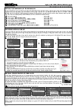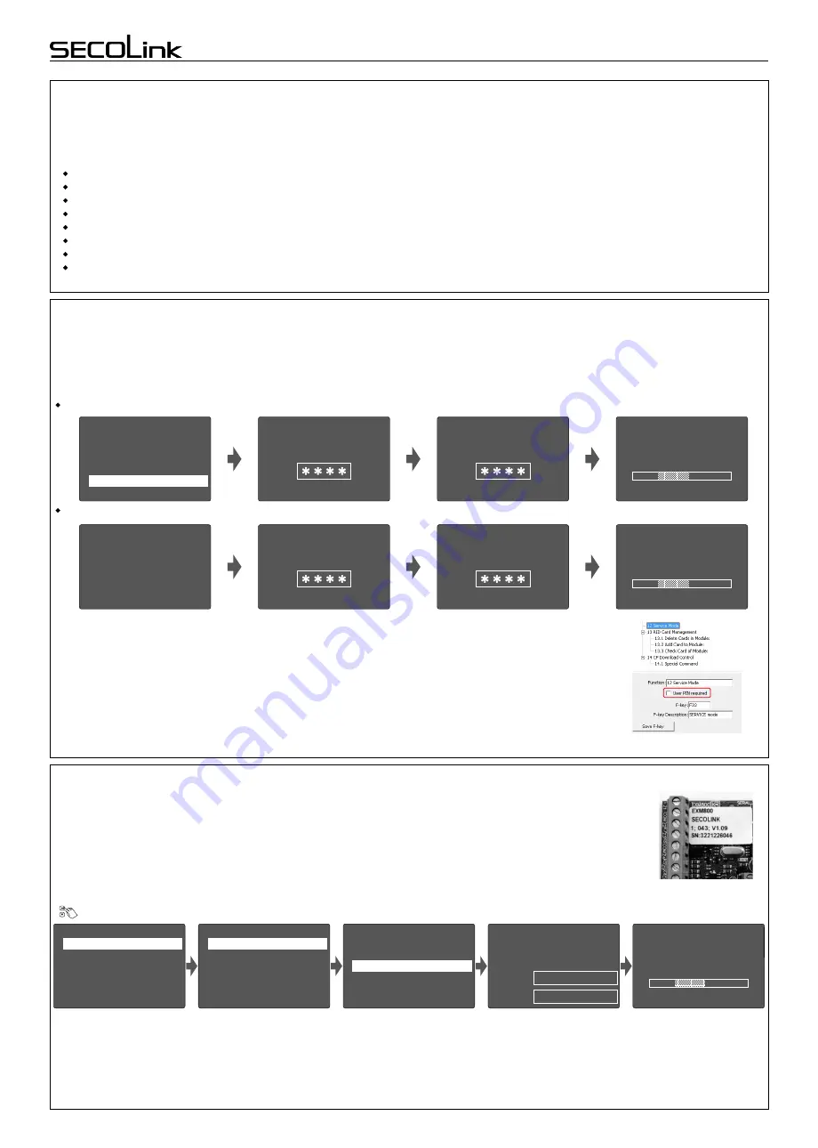
ENTERING SERVICE MODE
It is recommended to use the computer and software MASCAD for the installations with few partitions and more than 10 zones
. For
simple
installations it is
more
efficient to change the template manually by using
the
LCD keypad.
Changes should be made
in service mode when
the system is disarmed.
For security reasons permission to access the service mode has to be
enabled by entering user's PIN
(default PIN codes: first user -
0001
,service -
0000
)
.
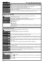
There are 2 ways to enter the service mode:
by navigating
the
menu:
by using the F-key:
Fig. 2
Tab
F - key
s
Short programming manual - basic information
Intruder alarm system
5
4
Controls
3
Event Log
2
Test
1
Settings
Main Menu
Se
r
vice Mode
Press arrows to navigate
Service Mode
F-key
F33
System with
KM24, KM24A
, KM24G keypads
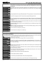
DEFAULT ADDRESSES OF THE MODULES
S
ystem manufacturer has provided the modules with default addresses assigned to them. This is done in order to simplify the process of
registration for most frequently used combinations of
the
system modules (such as PAS808
M
, KM20B, GSV
6U
or PAS816, KM24
A
,
EXM800,
EXT116S
, GSV
6U
). While registering modules of a different type, you will not need to enter serial numbers of each module, as
the system will automatically assign default addresses for the modules that are listed below:
There is an option to set the system without entering the required user's PIN that is needed to access the
service mode.
To do this, you will need to modify the template by using
software
MASCAD
:
Enter User PIN
Enable
Service
Entering
Service
Enter service PIN
Service
Mode
Enter User PIN
Enable
Service
Entering
Service
Enter service PIN
Service
Mode
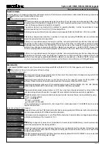
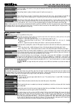
1. Connect the keypad to your computer using a USB cable
.
2. Establish
a
connection with
the
computer
. Using the keys with arrows go to the menu:
Service Mode
}
Project Loading
}
Start connection with PC
.
3. Download data from the keypad to software MASCAD (use the tab
Project data sending/receiving
).
4.
Go to
F-key
tab
.
5.
Click on row
F33 SERVICE Mode
and
uncheck the box
User PIN required
from the settings
(see Fig. 2).
6. Upload the customized project back to the keypad
(use the tab
Project data sending/receiving
)
.
MANUAL
REGISTRATION OF MODULES
Control panel
PAS808M
support
s
up to 7 modules
and control panels
PAS8
16, PAS832, P16, P32, P64
supports up
to 15 modules
(
)
. If there are
a
few modules
with
incl. enabled virtual modules EXT116VM on P series control panels
the same default addresses
in the system (
for example: several
EXM800 or
GSV6U
and LAN800
modules
),
only the
module with a
greater
serial number will
be registered during the
module
registration procedure.
All remaining
modules (not registered) must be registered manually.
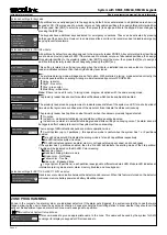
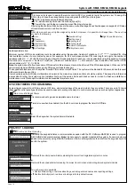
To register the module, an installer must enter
the
service mode, t
ype in
a 10 digit serial number, which is on the
module’s label
(see Fig. 3)
,
then press
the
[ENT]
key to jump to second row, enter module address of the system
,
and
press
[ENT]
again to start registration.
Fig. 3 EXM800 label
Registering
Manual
registration
Serial No. 3221226046
Address
5
5
6
4
Set Language
3
Project Loading
2
Report Settings
Service Mode
Unregister Modules
Programming Wizard
1
System Setup
5
6
4
PGM outputs
3
Zones
2
Partitions
System Setup
System Times
Security Settings
1
Modules
3
2
Automatic registration
Modules
1
Module settings
Manual registration
The module will start to flash its address with the green LED after a correct serial number and address is entered.
If a mistake was made
while entering serial number
,
the module will stay unregistered. If a mistake was made while entering the address which is used by another
module, then the new module will overtake this address and the other module will stay unregistered.
Note:
a
registered module
will
slowly flash its address on a green LED, which is located on the module's PCB (
excluding keypads and
a
control panel
).
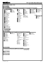
Service Mode
}
System setup
}
Modules
}
Manual registration
Page 2
For all control panels
For the keypad
KM20B, KM
24, KM25
For the keypad with a temperature sensor
KM24A, KM24G
For extra power supply module
PWR20
For the zone/PGM expansion module
EXM800
For the remote control module
EXT016
,
EXT116S
,
EXT216
For the proximity reader
PRO
X8
For the GSM/GPRS, LAN communicator
GSV6U
,
GSVU
, LAN800
- address
00
;
-
address
01
or
03
;
-
address
02
or
04
;
- address
04
or none;
-
address
05
;
-
address
06
;
-
address
06
;
-
address
07 or 11
(for GSVU)
;


