background image

CN1

CN2

10 11 12

1   2   3   4   5   6   7   8   9

SAFETY GATE

SAFETY GATE

SWING 2

2

10

8

2

9

10

-

+

12

13

CN2

10 11 12 13 14 15

1   2   3   4   5   6   7   8   9

Working with DIP 4 placed to ON position and exclusively in working 
times self-learning mode.

ENCODER (SAFETY GATE) 

MANAGEMENT ACTIVATION

After executing the four programming steps of the card, after connecting the encoder of both the motors and 
executing themotor torque adjustments using trimmer RV1 and/or mechanical adjustment devices (by-pass 
valves), place   DIP 4 to   ON position and repeat the programming procedure.

If necessary it’ s possible to disable   the SAFETY GATE management placing DIP 4 to OFF position, without 
repeating the self-learning times procedure.

SAFETY GATE (ENCODER), FLASHING LAMP
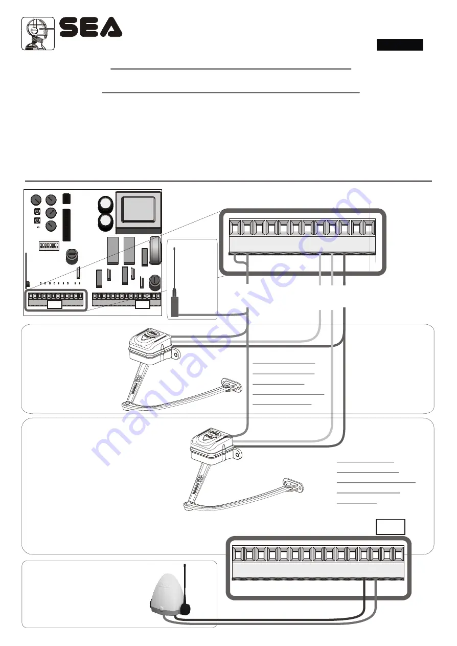
Encoder 2

The encoder (Safety Gate) is a 
s y s t e m   f o r   o b s t a c l e s  
detection. It is set in the factory 
on a middle level but   can be 
modified.   Low sensibility 
levels do not   allow a fast 
inversion as   required by the 
En12453 rules.
Connect the encoder 2 as in 
the picture.


NOTE: Only in 
working times 
selflearning 
mode (DIP8 OFF 
and DIP4 ON)

Encoder 1

The encoder (Safety Gate) is a system for 
obstacles detection.
Connect the encoder 1 as in the picture.
The Encoder function can be used in single leaf 
modality.

Note: With the PALM device or through the 
Trimer Rv4 on board of the control unit. it is 
possible to adjust the sensibility of the 
encoder on a scale from 0 to 15, where 0 
indicates the max. sensibility during the 
inversion.
Note: Every time when there is no current 
supply and after every osbstacle the 
automation, when no limit switches are 
installed, will proceed slowly until it reaches 
the stop. 

Note: Only in 
working times 
selflearning mode 
(DIP8 OFF and 
DIP4 ON)

Flashing lamp (230V  50W   
MAX)

Connect the flashing lamp as in 
the picture.
It’s possible to ebable a pre-
flashing of 3 seconds putting DIP2 
to ON position.

~

30

Brown

White

White

Green

English

After an Encoder 
intervention and in case 
of power supply failure,  
the leaves will proceed at 
reduced speed until they 
reached their referring 
stops. 

Sistemi Elettronici

di Apertura Porte e Cancelli

International registered trademark n. 804888

®

REV 07 - 05/2009

1

2

Antenna

C o n n e c t  
the antenna 
as in the 
picture.

The sensibility of the 
encoder is adjustable 
through the Trimmer 
Rv4 on board of the 
unit,   see pag.27.

Summary of Contents for SWING 2

Page 1: ... START ANTENNA PHOTOCELLS ELECTRIC LOCK CONNECTIONS 28 POWER SUPPLY AND MOTOR CONNECTIONS 29 ENCODER SAFETY GATE MANAGEMENT ACTIVATION 30 SAFETY GATE ENCODER FLASHING LAMP CONNECTIONS 30 WORKING TIMES SELFLEARNING ON SWING GATE 31 WORKING TIMES ADJUSTMENT WITH TRIMMER ON SWING GATE 34 RADIO TRANSMITTERS MEMORIZING 35 RADIO TRANSMITTERS CANCELLATION 35 SAFETY LOOP CONNECTION 36 TROUBLE SHOOTING 37 ...

Page 2: ...nternational registered trademark n 804888 REV 07 05 2009 CN1 CN2 RL1 RL2 F1 F2 P1 P2 Rv1 Rv2 Rv3 U1 U2 DIP LED5 LED8 LED9 LEDP LED2 LED3 LED4 Rv4 LED1 LED6 LED7 CMR CNP CN3 CN3 Connector 24 V Photosync Rv1 Motor power adjustment Rv2 Time of slowdown adjustment and leaf delay management Rv3 Pause time adjustment Rv4 Encoder sensitivity and working times adjustment P1 Working times learning push bu...

Page 3: ...ing Cl sing o Common a p Flashing l m 230V 50W max Encoder 1 2 3 4 5 6 7 8 9 10 1112 Photoc ell 24V TX l tr l k E ec ic oc 2 Photoc ll e r a Pedes t i n STAR T STOP Comm on n e A t nna TA S RT 1 Photoc ll e En od r 2 c e En od r 1 c e C m o o m n i L ne Neu r l t a Pre flashing Note Bridge all unused N C contacts English Sistemi Elettronici di Apertura Porte e Cancelli International registered tra...

Page 4: ... adeguate rigid and or flexible tubes Keep always separate the connection cables of low voltage accessoires from those of 115 230V power supply To avoid any interference use separate casings 2 Max Length of the power supply cable between control unit and motors is 10m using cables with 2 5 mm section SWING 2 24 ACCESSORES TECHNICALFEATURES Kind of accessories Inom absorbed stand by SIGNALreceivers...

Page 5: ...closing phase reverses the movement SAFETYSEMI AUTOMATIC LOGIC Astart impulse opens the gate Asecond impulse in opening phase reverses the movement When the gate is in opening position another impulse is required in order to reclose the gate Astart impulse during the closing phase reverses the movement NB Ruotare il trimmer Rv3 tutto in senso orario OFF FUNCTIONING LOGICS SELECTION DIP1 E Rv3 DIP1...

Page 6: ...his function is activated motor speed reduces slowly before the gate reaches the limit switch stop or before the operating time ends This function is designed in order to get the leaf gently closer to the mechanical stops avoiding any noisy clash The closing speed is fixed while the slowdown time can be adjusted using the trimmer Rv2 5 ON 6 ON REVERSING STROKE This function to be used exclusively ...

Page 7: ...ust be executed so that there is no crushing danger for people or objects and in any case in accordance with the law in force on the matter SLOWDOWN TIMEADJUSTMENT LEAF DELAYIN WORKING TIMES MODE WITH TRIMMER This trimmer has a double functionality depending on the selected working mode In working times selflearning mode it allows to adjust the length of slowdown time In working times manual adjus...

Page 8: ...sed the automation reverses its movement if in closing phase To use the photocells self testing connect the of the TX photocell 1 with contact 11 instead of 10 Note When not used make a jumper between contact 7 and 2 of Cn1 Note With the PALM device it is possible to set this photocell as PHOTOCLOSE that means that if occupied during the pause the automation interrupts the same and recloses immedi...

Page 9: ... 2 Com N Power supply Power supply connection P PHASE N NEUTRAL M M SWING 2 3 2 8 7 4 5 6 16 9 10 11 16 15 14 Com M M P MOTORS CAPACITORS POWER SUPPLY Example Motor 1 Motor 1 outputs M OPENING CLOSING Com COMMON English Sistemi Elettronici di Apertura Porte e Cancelli International registered trademark n 804888 REV 07 05 2009 29 ...

Page 10: ...IP8 OFF and DIP4 ON Encoder 1 The encoder Safety Gate is a system for obstacles detection Connect the encoder 1 as in the picture The Encoder function can be used in single leaf modality Note With the PALM device or through the Trimer Rv4 on board of the control unit it is possible to adjust the sensibility of the encoder on a scale from 0 to 15 where 0 indicates the max sensibility during the inv...

Page 11: ...mum value ONLY during the selflearning phase Immediately afterwards set a motor torque value which can assure the anticrushing safety in accordance with the law in forcei WARNING THIS PROCEDURE IS POTENTIALLY DANGEROUS AND MUST BE EXECUTED EXCLUSIVELY BY SPECIALIZED STAFF UNDER SAFETYCONDITIONS PHASE 2 Disconnect the power supply Fig 1 release the gate Fig 2 and place the leaves at half open posit...

Page 12: ...op in opening press once again P1 Fig 8 At this point motor M2 also will start an opening cycle When the leaf will reach the mechanical stop in opening push once again P1 Fig 9 If the motos starts to open the gate disconnect the power supply again and reverse the motor phases Execute the same kind of connection on motor M1 Repeat the programming procedurerogrammazione fase 2 Fig 6 P1 P1 M2 M1 Fig ...

Page 13: ...i crushing safety in accordance with the law in force If after adjusting the motor torque the working time is not enough the leaf doesn t open close completely repeat STEP2 setting the motor torque value as for the usual use of the automation Adjust the slowdown time if enabled using trimmer Rv2 NOTE assure that in SAFETYGATE assistance Encoder DIP4 is placed to OFF position 4 SWING 2 33 WORKING T...

Page 14: ...ease trimmer Rv4 rotate clockwise and give again a STARTimpulse On the contrary if the gate executes a too long complete opening closing cycle decrease trimmer Rv4 rotate counter clockwise Repeat the procedure until the gate will reach the complete and requested opening and closing cycle When this mode is on it s possible to adjust the leaf delays using trimmer Rv2 NOTE WHEN THIS MODE IS ON THE US...

Page 15: ... the button P2 PCode LEDPwill switch on 2 Press the button P1 PTime LEDPwill start to flash quickly If no further code is memorized within 10 sec The led will switch off automatically getting out of the memorizing procedure it will be deleted 4 flashes P1 Give an impulse with the radio transmitter using the button which will be linked to the pedestrian start impulse The Led will execute 2 long fla...

Page 16: ... N C English SAFETY LOOP CONNECTION Loop exit 1 Connecting scheme of loop 1 5 Contact start n o 2 Common Loop exit 2 Connecting scheme of loop 2 5 Contact start n o 2 Common Safety loop Connecting scheme of loop 3 7 Contact photocell n c 2 Common Loop 2 Loop 3 36 Sistemi Elettronici di Apertura Porte e Cancelli International registered trademark n 804888 REV 07 05 2009 C1 CONTACT OPEN C2 CONTACT C...

Page 17: ...he obstacle If encoder function is on decrease its sensitivity Gate doesn t reach the complete open close position a Programming error b Gate is stopped by an obstacle c The fiting geometry is inadequate d In manual adjusting mode with trimmer Rv4 a Repeat the programming b Remove the obstacle c Check fitting geometry following the operator installation manual d Rotate Trimmer Rv4 clockwise Gate o...

Page 18: ...rranty if it doesn t show any damage caused by an irregular use or by any modification or breaking The warranty is valid only for the original buyer NOTE THE MANUFACTURER IS NOT CONSIDERED RESPONSIBLE FOR EVENTUAL DAMAGES CAUSED BYIRREGULAR WRONG OR UNREASONABLE USE SEA reserves the right to make any required modification or change to the products and or to this manual without any advanced notice ...

Page 19: ...nty 36 months will be extended for further 24 months up to a total of 60 months when it is acquired the certificate of warranty which will be filled in and sent to SEA s r l within 30 days from the purchase date The electronic devices and the systems of command are guaranteed for 24 months from the date of manufacturing In case of defective product SEAundertakes to replace free of charge or to rep...

Reviews: