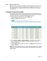
background image


Changing SNMP Settings 

4018055 Rev B 

39

Changing SNMP Settings 

Introduction 

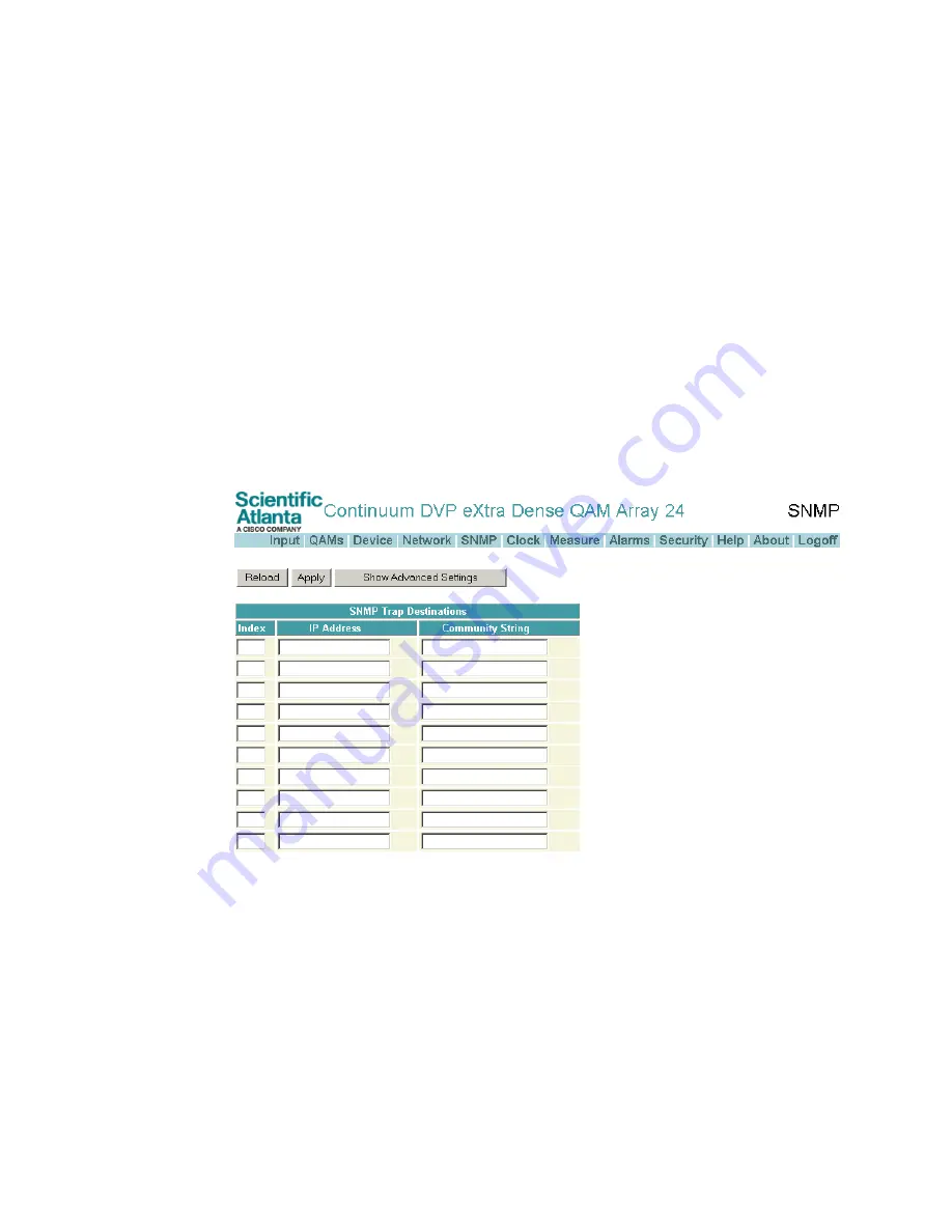
The SNMP Trap Destinations table on the SNMP page represents to which 
destinations IP address the traps are sent. Traps can be logged into the ROSA system 
as messages. More information concerning ROSA can be found in the ROSA User’s 
Guide. 


To Change SNMP Settings 

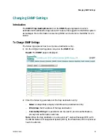
The following explains how to complete a destination entry. 
1


On the XDQA24 configuration site, click the SNMP link. 
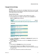
Result: The SNMP page is displayed. 


2


Enter the following parameters in the trap destination entry: 

-


Index: an object that uniquely identifies a trap destination entry 

-


IP Address: the IP address of the trap destination 

-


Community String: this parameter can be used to provide authentication, 
privacy and authorization services. 

Note: When the trap destination is a Copernicus™ element manager (EM) with 
the ROSA Network Management System (NMS), the IP address of the Copernicus 
has to be entered. 


Summary of Contents for Continuum DVP eXtra Dense QAM Array 24

Page 1: ...4018055 Rev B Continuum DVP eXtra Dense QAM Array 24 Configuration Guide...

Page 2: ......

Page 3: ...resent the tip of the flash points to the terminal device You may find this symbol affixed to the product This symbol indicates a protective ground terminal You may find this symbol affixed to the pro...

Page 4: ...For Your Safety iv 4018055 Rev B...

Page 5: ...use of any information in this document employs an invention claimed in any existing or later issued patent Copyright 2008 Cisco Systems Inc All rights reserved Printed in Belgium Information in this...

Page 6: ......

Page 7: ...Information 8 To View the System Information 8 Viewing the Dual QAM Card Information 9 Chapter 2 Securing the XDQA24 System 11 Introducing the Security 12 Configuring the Security System 13 Adding a U...

Page 8: ...9 Introduction 39 To Change SNMP Settings 39 Chapter 4 Viewing the Measurements 41 Introduction 42 Viewing the System and GbE Input Measurements 43 Viewing GbE Statistics 45 Viewing the Measurements p...

Page 9: ...s for Repair 72 Introduction 72 Obtaining an RMA Number and Shipping Address 72 Packing and Shipping the Product 73 Appendix B EIA Channel Numbers 75 EIA Digital Channel Numbers 76 Appendix C Cisco Wi...

Page 10: ......

Page 11: ...d in this guide is used to monitor and or manage Cisco equipment Certain safety precautions should be observed when operating equipment of this nature For product specific safety requirements refer to...

Page 12: ......

Page 13: ...uration guide the personnel should have a basic knowledge about the technology used in relation to this product Related Publication Refer to the following Scientific Atlanta publications for more info...

Page 14: ......

Page 15: ...A24 System Introduction This chapter provides an introduction to the Continuum DVP eXtra Dense QAM Array system In This Chapter General 2 Functional Description 3 Modular Concept 4 Introducing the Web...

Page 16: ...roadcast services The XDQA24 system is an ideal bridge between flexible IP and Gigabit Ethernet based backbone networks and existing QAM set top boxes Its hot swappable modular design allows for scala...

Page 17: ...RF Buffer Routing PCR QAM Mod QAM Mod Up converter Buffer Routing PCR QAM Mod QAM Mod Up converter RF RF Buffer Routing PCR QAM Mod Buffer Routing PCR QAM Mod QAM Mod Up converter RF QAM Mod Up conver...

Page 18: ...t PSU Quad Channel QAM Card Continuum DVPeXtra Dense QAMArray 24 Housing The XDQA24 housing is a compact modular 1RU high 19 inch housing provided with a system controller input board which controls t...

Page 19: ...4 system has 1 1 redundancy concept This means the system can tolerate the removal or failure of one of the power supplies and remains fully operational Each power supply generates a 12V dc supply vol...

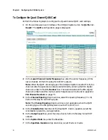
Page 20: ...output signal contains two combined adjacent QAM channels You can install a maximum of six Quad Channel QAM Cards inside the XDQA24 Housing When installing a Quad Channel QAM Card in the housing all...

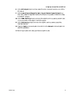
Page 21: ...interface of the device will be opened The following illustration shows the opening page of the XDQA24 web browser user interface Notes When the security feature of the XDQA24 system is enabled a log...

Page 22: ...concerning the XDQA24 system is categorized on the About page The following steps explain how to view the system information of the XDQA24 1 On the web browser user interface of the XDQA24 system site...

Page 23: ...m click the QAMs link Result The QAMs page is displayed 2 Press the Card Versions command button Result The QAM Cards Version Information popup is displayed with the following information Serial Numbe...

Page 24: ......

Page 25: ...s chapter describes the security feature of the Continuum DVP eXtra Dense QAM Array system and gives information on how to configure this security feature In This Chapter Introducing the Security 12 C...

Page 26: ...curity configuration Administrator full control with security configuration The XDQA24 system security is provided with three pre defined user accounts The table below shows these pre defined user acc...

Page 27: ...browser user interface of the XDQA24 system click the Security link Result The Security page is displayed 2 Point to the Add User command button Result The Add Modify user details table is displayed...

Page 28: ...st 1 On the web browser user interface of the XDQA24 system click the Security link Result The Security page is displayed 2 In the User Accounts list point to the Modify command button in the row of t...

Page 29: ...ession timeout box enter the period of time the web browser user interface can remain unused before the authorization of the web browser user interface expires A timeout value between 1 and 99 minutes...

Page 30: ...e SNMPCommunity Settings The community strings used by the SNMP agent to monitor or to manage the device using SNMP can be changed The following procedure explains how to change the read and write com...

Page 31: ...rs 2 Enter the username of your account in the Username box 3 Enter the password in the Password box Result When the username and password are correct entered the web browser user interface becomes ac...

Page 32: ......

Page 33: ...apter describes how to configure the Continuum DVP eXtra Dense QAM Array system using the web browser user interface In This Chapter Changing the Device Settings 20 Configuring the GbE Input 25 Config...

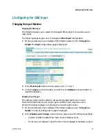
Page 34: ...ate the identification of the XDQA24 system in the application A name and location of maximum 50 characters can be given and can t contain the following characters Tip These parameters appear in the t...

Page 35: ...VBR SPTS streams Bitrates are updated each PCR interval Next to this a long term regulation is running CBR supports CBR SPTS streams The bitrate is calculated at startup of the stream Only a long term...

Page 36: ...name box enter a name for the XDQA system 4 In the Device location box enter the location for the XDQA system 5 In the Enabled drop down select Yes to enable the Keep Alive feature or No do disable th...

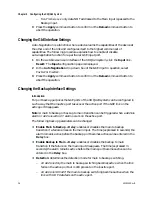
Page 37: ...the XDQA24 System with a Time Sever The following procedure explains how to synchronize the XDQA24 system with a time server 1 On the web browser user interface of the XDQA24 system click the Clock l...

Page 38: ...ton This function has no influence on the running synchronization cycle The Time Synchronization with Server should be enabled Example The clock of the XDQA24 system should be synchronized every day a...

Page 39: ...he Apply command button to confirm or the Reload command button to abort the operation Enabling Loop Through This setting configures the system to act as a bridge between the two inputs Therefore all...

Page 40: ...he XDQA24 system can be configured in such a way that the inactive port takes over the active port if the GbE link on the active port disappears Note A main to backup or backup to main transition can...

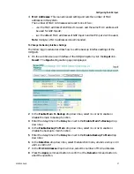
Page 41: ...4 system click the Input link Result The Input configuration page is displayed 2 In the Enable Main To Backup drop down box select Yes or No to enable or disable the main to backup function 3 Enter th...

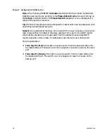
Page 42: ...e delay time to switch from main to backup or backup to main is bigger then indicated in the delay settings This is due to the IGMP reports that must be sent after a port is activated The time needed...

Page 43: ...er interface of the XDQA24 click the Network link Result The Network page is displayed 2 Change the IP Address and or Net Mask of the Ethernet port in question or the Gateway of the system 3 Press the...

Page 44: ...Chapter 3 Configuring the XDQA24 System 30 4018055 Rev B...

Page 45: ...XDQA24 system is predefined on 6 MHz The channel spacing for an ITU A configured XDQA24 system can be set to 7 or 8 MHz Notes The lower channel center frequency of an ITU B or ITU C configured XDQA24...

Page 46: ...ge a message box is displayed Spectrum Inversion The spectral inversion can be enabled to invert the asymmetric QAM spectrum if the set top box cannot invert the spectrum itself The spectral inversion...

Page 47: ...ht cause signal lock problems on some set top boxes This can be solved by using pseudo random binary sequence PRBS stuffing packets Note PRBS stuffing packets are stuffing packets filled with random d...

Page 48: ...al channel number in the Ch Number box The relation between the EIA digital channel numbers and the channel center frequencies can be found in appendix EIA Channel Numbers on page 75 3 In the Channel...

Page 49: ...annel in question Perform this step for both RF outputs 10 In the PRBS Stuffing drop down box of the QAM card in question select Enable or Disable Perform this step for both RF outputs 11 In the Inter...

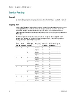
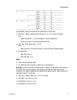
Page 50: ...f the 24 QAM outputs A mapping table defines the mapping rules between UDP ports program numbers and PID ranges The following table reflects the relation between the Quad Channel QAM Card number slot...

Page 51: ...PID Map value Program Number in case of default mapping table ES PID Range Start PMT PID 1 End PMT PID 15 Notes The UDP port is always even An UDP port with program number 0 or 1 is not allowed Exampl...

Page 52: ...transport stream in the network The Program Association Table PAT includes the Transport Stream identifier 1 On the XDQA24 configuration site click the QAMs link Result The QAMs page is displayed 2 I...

Page 53: ...o complete a destination entry 1 On the XDQA24 configuration site click the SNMP link Result The SNMP page is displayed 2 Enter the following parameters in the trap destination entry Index an object t...

Page 54: ...ion Notes When a destination entry is not complete or you have to disable an entry press the Show Advanced Settings command button and select NotInService in the Row Status drop down box To delete a d...

Page 55: ...apter outlines the measurement feature of the Continuum DVP eXtra Dense QAM Array system In This Chapter Introduction 42 Viewing the System and GbE Input Measurements 43 Viewing GbE Statistics 45 View...

Page 56: ...ment system The measurement results are categorized on the measure page of the web browser user interface The XDQA24 measurements are divided in 5 groups viz The system measurements The GbE input meas...

Page 57: ...the GbE Input System bandwidth used Mbps Actual bitrate of all fitted Quad Channel QAM cards System bandwidth available Mbps Maximum bitrate achievable with the fitted Quad Channel QAM Cards Cards fit...

Page 58: ...mit bitrate Total outgoing bitrate on the port Error bitrate Total bitrate of errored data on the input Note When another measurement sub page is selected press the Overview command button to select t...

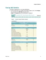
Page 59: ...followng explains how to view the GbE Statistics 1 On the web browser user interface of the XDQA24 system click on the Measure link and point to the GbE Stats command button Result The Measure page w...

Page 60: ...had either a bad Frame Check Sequence FCS with an integral number of octets FCS Error or a bad FCS with a non integral number of octets Alignment Error Packets of 64 octets incl bad pkts represents t...

Page 61: ...127 octets incl bad pkts represents the number of frames transmitted by the corresponding port which had a length between 65 and 127 octets Packets of 128 255 octets incl bad pkts represents the numb...

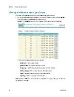
Page 62: ...e Measure page with the measurements per output is displayed The following measurements can be checked QAM card The number of card QAM channel The QAM channel number Frequency The RF output center fre...

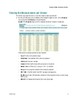
Page 63: ...am is displayed The following measurements can be checked Type The incoming stream type IP address The address of the incoming stream UDP port The port number Output Which QAM channel the program is r...

Page 64: ......

Page 65: ...troduction This chapter describes the procedure to check the alarms using the web browser user interface and contains a list with explanation of all of Continuum DVP eXtra Dense QAM Array system alarm...

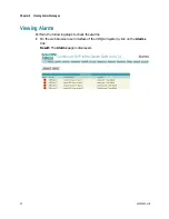
Page 66: ...ng Alarm Messages Viewing Alarms Perform the following steps to check the alarms 1 On the web browser user interface of the XDQA24 system click on the Alarms link Result The Alarms page is displayed 5...

Page 67: ...view an alarm log on the Alarms page Note Several alarm subjects are made up of the Quad Channel QAM card number to which the alarm applies followed by the alarm For example the RF Output alarm for c...

Page 68: ...g correctly The alarm clears when the temperature is back in specification X represents the QAM card position and Y the card temperature Alarm Qam Card X Temp major Ref Temperature Critical Detail Tem...

Page 69: ...information The QAM card should be left for at least 1 minute to see if the error clears If after 1 minute the alarm still persists then the card should be removed and re inserted again If this action...

Page 70: ...ircuit is out of specification The board should be left for at least 1 minute to see if the error clears If after 1 minute the alarm still persists then the card should be removed and re inserted agai...

Page 71: ...U fails and the BACKUP PSU became active Remove the MAIN PSU and reinsert the module after a while If this action does not clear the alarm then the PSU module should be replaced Alarm Alarm Backup Psu...

Page 72: ...s an illegal value then this alarm is raised X represents the QAM card number Alarm Qam Card X Configuration Ref Output Y Channel Spacing missing Detail Channel Spacing default to Z If a Channel Spaci...

Page 73: ...m is raised A Scientific Atlanta representative should be contacted X represents the QAM card number and Y the RF output number Alarm Qam Card X Configuration Ref Output Y Z Signal missing Detail Sign...

Page 74: ...X Configuration Ref Output level out of range Detail OP Lev Min Max actual The output level has been set out of range The output level is set to the minimum or maximum value Set the output level betwe...

Page 75: ...hannel Alarm Si processor Ref Multiple routes for program Detail IP Input Stream Qam Channel and Qam Channel A program has been routed to more than one output channel Alarm Si processor Ref Program al...

Page 76: ...to the QAM channel and the QAM card is dropping packets of data then this alarm will be raised The amount of data that can be routed to a QAM channel is dependant on the QAM mode 64 or 256 and the ITU...

Page 77: ...oes not clear the alarm then a Scientific Atlanta representative should be contacted The alarm clears when the VCO locks X represents the QAM card number Alarm Qam Card X VCO2 Ref VCO2 Output Y Unlock...

Page 78: ...he signal format is set to normal this warning is cleared X represents the QAM card number and Y the RF output number Alarm Qam Card X Misc Ref Upper channel Output Y mute Detail This warning shows th...

Page 79: ...d Troubleshooting This part provides information to assist you in maintaining and troubleshooting your Continuum DVP eXtra Dense QAM Array system In This Chapter Maintaining the Equipment 66 Troublesh...

Page 80: ...ance is recommended Frequency Maintenance Required Weekly Check all parameters Quarterly Make sure all cables are mated properly Inspect cables for stress and chafing Make sure all retaining screws ar...

Page 81: ...ses Solutions MAIN PS LED indicator is off No MAIN PSU installed Install a MAIN PSU MAIN PSU connection is loose Check that the main power connection is secure Loss of source power main PSU Check that...

Page 82: ...ALARM LED is on Pending alarm or error detected by the CPU module Troubleshoot the alarm or error message All LED indicators illuminates yellow The device is in startup state Please wait The device is...

Page 83: ...55 Rev B 69 A Appx auto letter Appendix A Customer Information Introduction This chapter contains information on obtaining product support In This Appendix Product Support 70 Return Products for Repai...

Page 84: ...Care Broadband Services Atlanta Georgia United States For Technical Support call Toll free 1 800 722 2009 Local 770 236 6900 Press 2 at the prompt For Customer Service or to request an RMA number call...

Page 85: ...3845 2514 E mail luiz fattinger sciatl com Mexico Central America Caribbean Mexico For Technical Support call Telephone 52 3515152599 Fax 52 3515152599 For Customer Service or to request an RMA numbe...

Page 86: ...pping address 1 Contact a customer service representative to request a new RMA number or revalidate an existing one Refer to the earlier section titled Support Telephone Numbers to find a customer ser...

Page 87: ...You are responsible for delivering the returned product to Scientific Atlanta safely and undamaged Shipments damaged due to improper packaging may be refused and returned to you at your expense Do no...

Page 88: ......

Page 89: ...ppx auto letter Appendix B EIA Channel Numbers Introduction This appendix provides a table showing the relations between EIA channels numbers and channel center frequency In This Appendix EIA Digital...

Page 90: ...3 0 4 69 0 73 519 0 5 79 0 74 525 0 6 85 0 75 531 0 7 177 0 76 537 0 8 183 0 77 543 0 9 189 0 78 549 0 10 195 0 79 555 0 11 201 0 80 561 0 12 207 0 81 567 0 13 213 0 82 573 0 14 123 0 83 579 0 15 129...

Page 91: ...05 0 41 327 0 110 711 0 42 333 0 111 717 0 43 339 0 112 723 0 44 345 0 113 729 0 45 351 0 114 735 0 46 357 0 115 741 0 47 363 0 116 747 0 48 369 0 117 753 0 49 375 0 118 759 0 50 381 0 119 765 0 51 38...

Page 92: ...Appendix B EIA Channel Numbers EIA Channel No Center Frequency No Offset EIA Channel No Center Frequency No Offset 66 477 0 135 861 0 67 483 0 136 867 0 68 489 0 137 873 0 69 495 0 78 4018055 Rev B...

Page 93: ...ter Appendix C Cisco Wideband Applications Introduction This appendix outlines the set up of the Continuum DVP eXtra Dense QAM Array 24 system for use into Cisco Wideband applications In This Appendix...

Page 94: ...a typical Cisco Wideband application Defining Streams When the XDQA24 system participates into a Cisco Wideband application the following setup should be made Define streams as data streams with a Dat...

Page 95: ...uring the Quad Channel QAM Card on page 31 For ITU B QAM encoding set the Interleaving parameter to I 32 J 4 The procedure to change the Interleaving parameter can be found in topic Configuring the Qu...

Page 96: ......

Page 97: ...has been focused specifically on conditional access DVP digital video platform E EEPROM electrically erasable programmable read only memory ES elementary stream F FPGA field programmable gate array G...

Page 98: ...access control The layer in the OSI model above the physical layer It defines media access control methods and parameters for access to the physical media MPEG Motion Picture Experts Group A joint com...

Page 99: ...thorization A form used to return products ROSA RCDS open system architecture RU rack unit RU is the measuring unit of vertical space in a standard equipment rack One RU equals 1 75 44 5 mm S SFP smal...

Page 100: ...allows a subscriber to use the remote control to select purchase and view an event Once purchased the viewer can then forward reverse pause and play the event just as he or she would with a VCR X XDQ...

Page 101: ...ter 30 Lower Channel Signal Format parameter 30 Cummunity String parameter 35 M Current time Changing 21 Maintenance 62 Current Time parameter 21 Mapping rule 32 Measurements 37 D Modular concept 4 De...

Page 102: ...35 SNMP Read Community parameter 15 SNMP settings Changing 35 Introduction 35 SNMP Write Community parameter 15 Symbol Rate parameter 30 System errors 58 T Troubleshooting 63 U User access level 12 U...

Page 103: ......
Page 104: ...Trademarks section of this document for a list of the Cisco Systems Inc trademarks used in this document All other trademarks mentioned in this document are the property of their respective owners Pr...

Reviews: