29
MPS4264
Section 4: Hardware
In normal, low-vibration environments the control pres-
sure does not need to be continuously supplied to this port
to hold the valve in the measurement mode. Applying
the pressure for 2-4 seconds will cycle the valve into the
measurement mode where it will stay until cycled out using
the Px CTL port. For high vibration environments, or where
it is absolutely critical that the module be held in measure-
ment mode, it is recommended to continuously supply the
pressure to this port to hold the valve in the desired state.
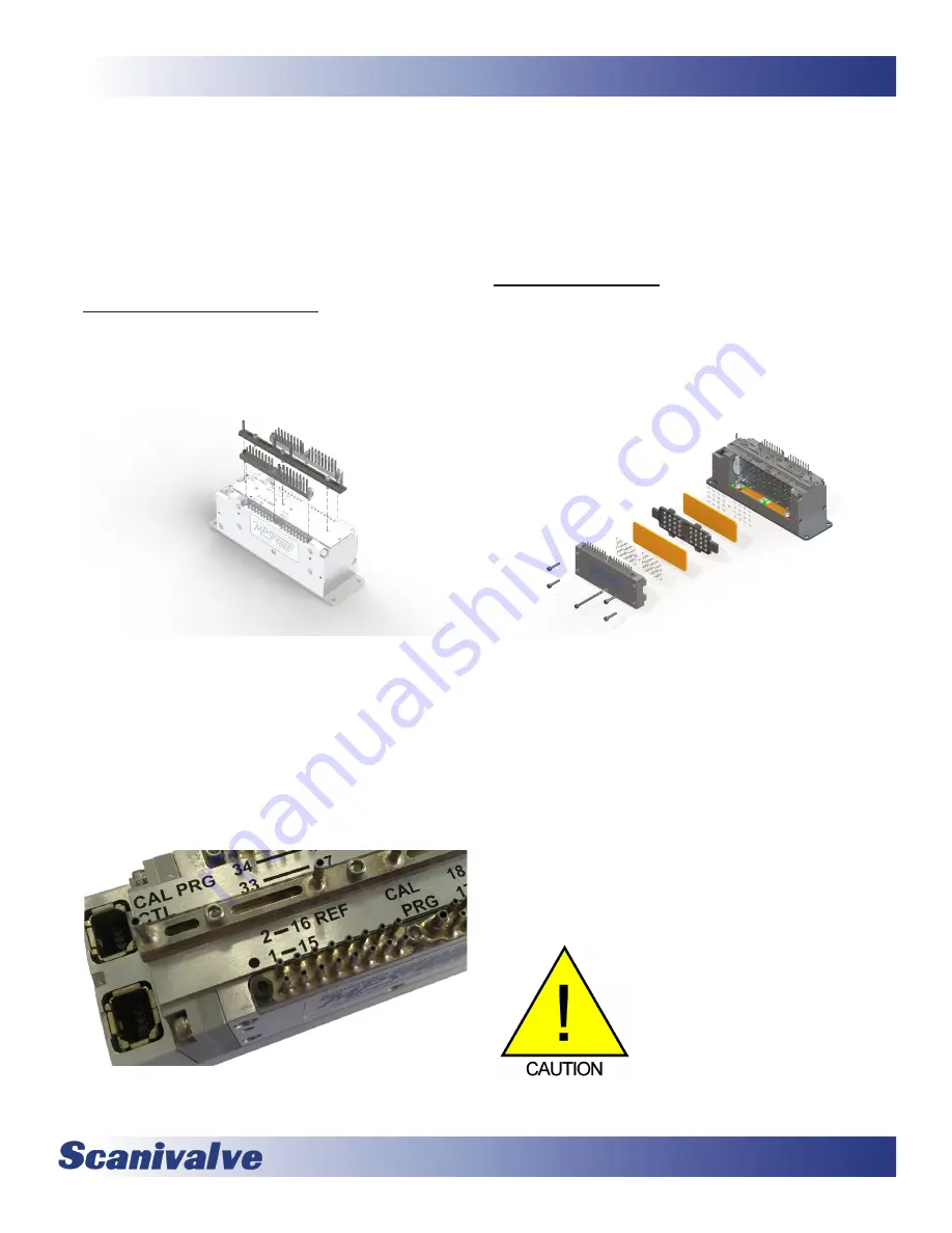
Removable Pressure Input Headers
All pneumatic inputs to the MPS are through three remov-
able input headers. Each of the three headers is held in
place with three #1-72 screws. A 1/16” Allen/hex wrench
fits the screws.
Figure 4-4: Removable Input Headers
The center header is polarized and cannot be installed
backwards. However, the two Px input headers are inter-
changeable and can be installed on the opposite sides. To
keep the manifolds unique and identified, the header for
inputs 1 through 32 has a single black oxide screw, whereas
all of the rest are nickle plated and silver in color. The
“correct” location for the black oxide screw is identified on
the MPS with a solid black dot. See Figure 4-5 below:
Figure 4-5: Header Identifier Mark
Be aware, that when the center header is removed the
identification plate will no longer be held in place. Like
the center header it is indexed and cannot be installed
backwards, but should be handled with care. The O-rings
supported in the identification plate should be kept clean
and watched to make sure they stay in place. Replace-
ment or additional headers can be purchase separately as
needed.
Calibration Valve
The MPS4264 module has two mirrored calibration valves,
each servicing 32 inputs. It is a slider-style valve with the
aluminum shuttle riding on ball bearings. The O-rings that
move with the valve shuttle ride on a proprietary plastic
“bearing plate” that minimizes friction to reduce the actua-
tion force and the wear on the O-rings.
Figure 4-6: Valve Exploded View
The calibration valve has two physical states, “Measure-
ment” and “Calibrate/Purge.” In measurement mode,
measurement pressures from the individual input tubes
is allowed to pass directly through the shuttle valve to the
pressure sensors. In calibrate/purge mode, the measure-
ment pressures from the individual input tubes are blocked
off and isolated from the pressure sensors. Instead, the
“CAL” input is manifolded and connected to the positive
side of all transducers. Additionally, the two “Purge” input
lines are connected to the input tubes on their respective
valves allowing the user to clear debris or moisture from
the input lines by blowing from the module back out to the
test article.
CAUTION! Do not cycle the valve
with pressure supplied to either the
CAL or PRG inputs.
It is uncommon, but possible, that while the valve is
Summary of Contents for MPS4264
Page 1: ...MPS4264 Miniature Pressure Scanner Hardware and Software Manual Software Version 2 07...
Page 2: ......
Page 3: ......
Page 6: ...INTENTIONALLY LEFT BLANK...
Page 12: ...6 MPS4264 Section 1 Specifications INTENTIONALLY LEFT BLANK...
Page 18: ...12 MPS4264 Section 2 Introduction INTENTIONALLY LEFT BLANK...
Page 32: ...26 MPS4264 Section 4 Hardware INTENTIONALLY LEFT BLANK...
Page 38: ...32 MPS4264 Section 5 Software INTENTIONALLY LEFT BLANK...
Page 81: ...75 MPS4264 Section 6 Maintenance INTENTIONALLY LEFT BLANK...
Page 86: ...80 MPS4264 Section 6 Maintenance INTENTIONALLY LEFT BLANK...
Page 87: ...81 MPS4264 Appendix INTENTIONALLY LEFT BLANK...


