


18
MPS4264
Section 3: Operation
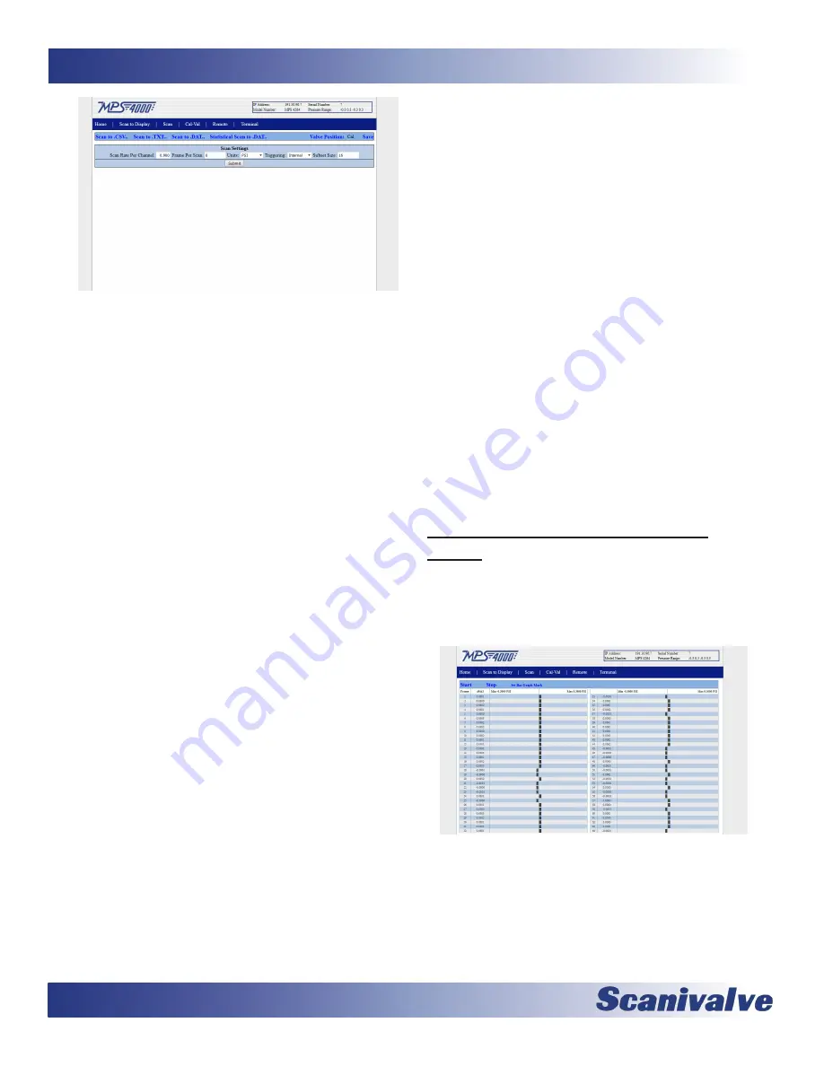
Figure 3-10: Web Server Scan Configuration
Screen
There are five configuration variables that you can set from
this screen. They are:
SCAN RATE PER CHANNEL: This sets the data output rate
in samples/channel/second (Hz).
FRAME PER SCAN: This sets the number of samples that
will be output for each time a “SCAN” command is
received.
UNITS: This is a selection box, allowing you to select the
pressure units the data will be output in.
TRIGGERING: This is a selection box, allowing you to
select the method that a each frame of data is initiated
by. There are four options:
INTERNAL - A scan is initiated, and subsequent frames
of data are scheduled using the MPS’s internal clock.
EXTERNAL - A scan is initiated, and subsequent frames
of data are schedule using an external trigger.
AUTOSCAN - The MPS will begin scanning and output-
ting data immediately on power up. See “Auto Scan
Option” on page 24 for more information.
Additionally, along the top of the screen there are four
“Scan to...” hyperlinks allowing you to initiate data collec-
tions using different methods. Those four options are:
SCAN TO .CSV: This generates a .CSV file that will be
saved to your local computer. This file will contain
ASCII data in a column format, with a column of data
for each pressure and temperature channel.
SCAN TO .TXT: This generates a .txt file that will be saved
to your local computer. This file will contain ASCII data
in a single “scrolling” format, with all data from each
frame of data printed out below the previous.
SCAN TO .DAT: This generates a .dat file that will be
saved to your computer. This file will be binary data
that will need to be converted to ASCII as a post
processing task.
STATISTICAL SCAN TO .DAT: This generates a .dat file
including pressure data and statistical analysis data that
will be saved to your computer. This file will be binary
data that will need to be converted to ASCII as a post
processing task. See “Statistical Scan Option” on page
24 for more information.
On the same header bar as the “Scan To...” hyperlinks
are two additional options. The “VALVE POSITION:” is an
indicator identifying the state of the pneumatic valve in
the MPS. It will either be “Cal” indicating the module is in
calibrate mode or “Px” indicating the module is in measure-
ment mode.
This is not automatically updated when the
valve state change, it must be manually polled. Do this by
single clicking on the blue “Valve Position” hyperlink.
The
final option in the header bar is the “SAVE” option. Clicking
this issues a SAVE command to the MPS taking the current
configuration from volatile RAM memory and saving it in
the non-volatile FLASH memory storage.
At the bottom of the screen is the “SUBMIT” button. For
any changes that are made to be sent to the MPS and take
effect, the “SUBMIT” button must be clicked. Without
clicking “SUBMIT” after making a change, the command
will not be sent to the MPS and the change will not be
effective.
Web Server: Scanning Data to the
Screen
After you have set up the scanning configuration you are
now ready to scan data to the display. On the blue naviga-
tion bar, click on the “Scan To Display” link. You will get the
following screen:
Figure 3-11: Web Server Scan to Display
Click on the “START” link. The bar graphs will display the
pressure as frames of scan data are sampled. Click on
“STOP” when finished. There are three important notes
about the “Scan to Display” function and how the bar-
graph works.
Summary of Contents for MPS4264
Page 1: ...MPS4264 Miniature Pressure Scanner Hardware and Software Manual Software Version 2 07...
Page 2: ......
Page 3: ......
Page 6: ...INTENTIONALLY LEFT BLANK...
Page 12: ...6 MPS4264 Section 1 Specifications INTENTIONALLY LEFT BLANK...
Page 18: ...12 MPS4264 Section 2 Introduction INTENTIONALLY LEFT BLANK...
Page 32: ...26 MPS4264 Section 4 Hardware INTENTIONALLY LEFT BLANK...
Page 38: ...32 MPS4264 Section 5 Software INTENTIONALLY LEFT BLANK...
Page 81: ...75 MPS4264 Section 6 Maintenance INTENTIONALLY LEFT BLANK...
Page 86: ...80 MPS4264 Section 6 Maintenance INTENTIONALLY LEFT BLANK...
Page 87: ...81 MPS4264 Appendix INTENTIONALLY LEFT BLANK...


