10
MPS4264
Section 2: Introduction
located in the center of the module protects the sensors
as much as possible from rapid temperature changes and
allows for very accurate temperature compensation.
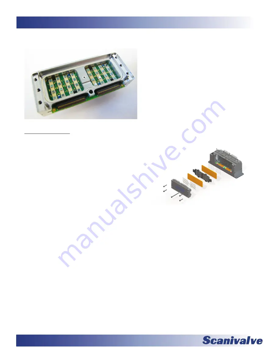
Figure 2-1: Pressure sensor overview
Pneumatic Valve
A single MPS4000 series module integrates two pneu-
matic valves, each supporting 32 channels. The valves are
located directly under the pressure inputs on each side of
the module. The valve supports four pneumatic states in
two physical states. In the “measurement mode” pressures
are directed in from the measurement inputs to the indi-
vidual pressure sensors. The other physical state, “calibrate
mode” provides three pneumatic states. They are:
1. Calibrate - A single pressure applied to the “CAL”
port is directed to the positive side of all 64 trans-
ducers.
2. Purge - Purge pressures applied to the two purge
inputs are directed out the 64 measurement ports
to clear any debris, particulate or moisture from the
inputs lines.
3. Isolate - The 64 pressure transducers are isolated
from the input lines and from the purge pressure.
The valve design is a sliding-type valve. An aluminum
shuttle populated with O-rings cycles back and forth
between two positions to achieve each of the physical
states. An interface between the sliding O-rings and the
aluminum stationary portion of the valve is a proprietary
compound that is extremely low friction. The O-rings
are supported completely to prevent any deformation
during a state change. Additionally, the valve shuttle is
supported on ball bearings to provide minimal friction and
maximum support. This design allows for low actuation
forces, minimal “stiction” - meaning the actuation forces
do not noticeably increase over time, and minimum wear.
Samples of the valve design were tested to over 1,000,000
cycles without any maintenance.
As a subset of the pneumatic option it can either be a
spring-driven “NPx” version or a “CPx” bi-directional
pneumatic driven version. The advantage of the “CPx”
pneumatic version is that it retains the same 65psi control
pressure that legacy ZOC33 analog pressure scanner
modules used. Two control pressure inputs are used, Px
CTL and CAL CTL. In the case of the spring-driven “NPx”
version a spring is constantly driving the valves into
measurement, or Px mode. This requires no control pres-
sures to be present for measurement and also prevents
the valve from unexpectedly or undesirably moving out of
measurement mode. The “NPx” version requires 90-120psi
control pressures which is common to the DSA line of prod-
ucts that Scanivalve produces.
All versions of the MPS4264 incorporate an optical sensor
used to determine the position of the valve. This can be
queried through the MPS’s software interface. The valve
position sensor only confirms that the valve is fully in the
measurement mode or not. It does not verify with 100%
certainty that the valve is in the calibrate mode.
Figure 2-2: Pneumatic valve exploded view
Summary of Contents for MPS4264
Page 1: ...MPS4264 Miniature Pressure Scanner Hardware and Software Manual Software Version 2 07...
Page 2: ......
Page 3: ......
Page 6: ...INTENTIONALLY LEFT BLANK...
Page 12: ...6 MPS4264 Section 1 Specifications INTENTIONALLY LEFT BLANK...
Page 18: ...12 MPS4264 Section 2 Introduction INTENTIONALLY LEFT BLANK...
Page 32: ...26 MPS4264 Section 4 Hardware INTENTIONALLY LEFT BLANK...
Page 38: ...32 MPS4264 Section 5 Software INTENTIONALLY LEFT BLANK...
Page 81: ...75 MPS4264 Section 6 Maintenance INTENTIONALLY LEFT BLANK...
Page 86: ...80 MPS4264 Section 6 Maintenance INTENTIONALLY LEFT BLANK...
Page 87: ...81 MPS4264 Appendix INTENTIONALLY LEFT BLANK...


