background image

36 


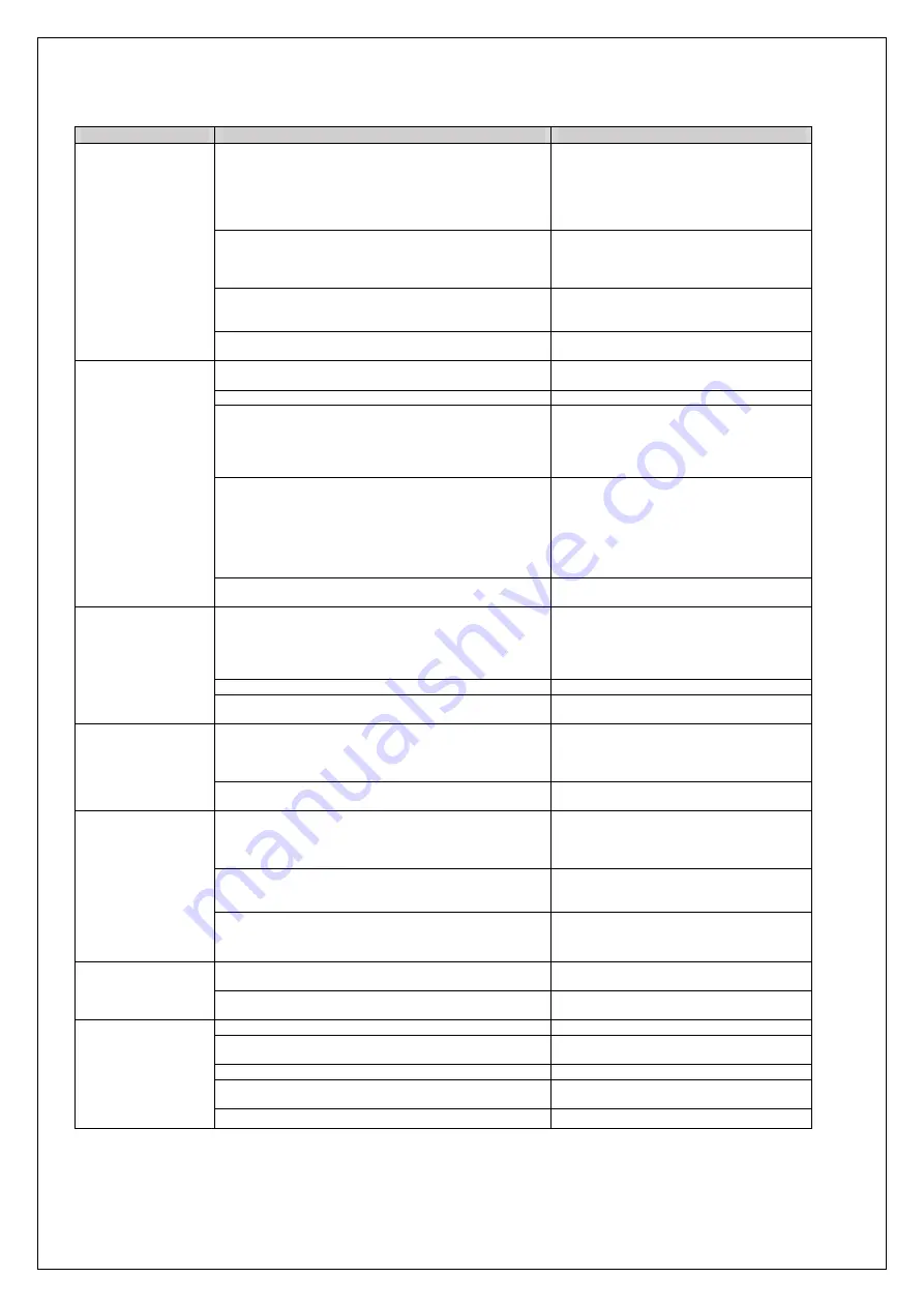
Table 3.2 Drive problems and corrective actions 

Problem 

Control Mode and Possible Cause 

Corrective Action 

Rollback at start 
 

Insufficient torque when the brake is released. 


• Increase the DC Injection Braking Current at 
Start using parameter S1-02. 
•Increase Torque Detection Gain (C4-01) in 
steps of 0.2.  
•Increase starting frequency (S1-00). 
•Increase Voltage offset (E1-03) in steps of 5V. 

DC Injection and brake timing are not optimized. 

Set the time for DC Injection Braking at Start 
(S1-04) as short as possible, and make sure that 
brake releases completely before the motor starts 
to turn. 

Motor torque is not fully established when the brake is released. 

Lengthen the Brake Release Delay Time (S1-06) 
and the time for DC Injection Braking / Position 
Lock at Start (S1-04). 

Motor contactor closes too late. 

Make sure that the contactors are closed before 
the Up/Down command is issued. 

Shock at start 

Motor starts rotating when the brake is not completely released 
or runs against the brake. 

Increase the DC Injection Braking Time at Start 
using parameter S1-04. 

Acceleration rate is changing too quickly. 

Increase C2-01. 

Starting torque influences the calculated slip. 

•Increase Slip Compensation Filter Time 
Constant (S2-06).  
•If the problem exists, increase the Slip 
Compensation Delay Time (S2-05) in steps of 
50ms. 

Starting torque is too much.  

•Increase Torque Detection Delay Time (C4-02) 
in steps of 50ms. 
• If the problem still exists, decrease Torque 
Detection Gain (C4-01). Note that decreasing 
C4-01 may result in motor stall and over-current 
fault. In this case, increase acceleration time 
(C1-01).  

 The starting speed is not optimized. 

Change S1-00 in steps of 0.1, and see its 
influence on shock.  

Shock at stop 

Brake is applied too early, causing the motor to run against the 
brake. 

•Increase the Delay Time to Close the Brake 
(S1-07). If necessary, also increase the DC 
Injection Braking Time at Stop S1-05.  
•If the problem still exists, increase zero speed at 
stop (S1-01). 

Motor contactor is released before the brake is fully applied. 

Check the motor contactor sequence. (S1-11) 

DC injection is not powerful enough to stop the motor 
efficiently. 

Increase DC injection at stop (S1-03).  

Jerk occurs due to 
overshoot when the 
motor reaches top 
speed. 

Too fast torque or slip compensation. 

• Increase the Torque Compensation Delay Time 
(C4-02). 
• Increase the Slip Compensation Delay Time 
(S2-06). 

The acceleration rate changes too quickly when reaching the 
selected speed. 

Decrease the Jerk at the End of Acceleration.  
Increase C2-02. 

Motor stops shortly 

(undershoot) when 

the leveling speed is 

reached. 


Not enough torque at low speed. 


If (E1-02=0), change it to 1 or 3.  
If E2-02=1, Increase E1-03.  
If E2-02=2/3, Increase (E1-10 to E1-13). 
Alternatively, you may increase E1-03.  

Too much slip compensation. 

Adjust the motor data, especially motor rated 
speed (S2-01) correctly. 
 

The deceleration rate changes too quickly when reaching 
leveling speed. 

Decrease the Jerk at the End of Deceleration. 
Increase C2-04. 

Motor or machine 
vibrates at high 
speed or top speed. 

Torque compensation responds too quickly. 

Increase the Torque Compensation Delay Time 
(C4-02). 

Rated speed is not set correctly 

Set the rated speed according to the motor 
nameplate. 

Motor or machine 
vibrates in the low 
or medium speed 
range. 

The output voltage is too high. 

Set E2-02 to 2or 3 and decrease E1-10 to E1-13. 

Torque compensation is responding too quickly. 

Increase the Torque Compensation Delay Time 
(C4-02). 

The value for the motor slip is set incorrectly. 

Check the Motor Slip value in parameter E2-02. 

The slip fluctuation is high. 

Increase the Slip Compensation Filter Time (S2-
06) in steps of 50ms. 

Vibration occurs only in regenerative mode.  

Increase C4-01.  


Table 3.3 Drive problems and corrective actions (closed-loop) 

Summary of Contents for L450S

Page 1: ...User Manual L450U L450S...

Page 2: ...this manual all functions are introduced and explained in detail The first chapter is dedicated to the initial settings and Auto tuning which calculates control parameters required to drive the AC mot...

Page 3: ...Hz Output Voltage V 3 phase 0 380V 0 100 Hz Rated Current A 14 18 24 31 Weight Kg 5 3 5 4 5 7 6 0 Mechanical Installation Dimensions The drive dimensions needed for mechanical installation are mentio...

Page 4: ...rive control circuits in SBT L450U and L450S models respectively In L450S model the drive can be used in a single phase It is also possible to set and run the drive via the digital operator without co...

Page 5: ...7 Figure 2 2 b SBT L450S I O block diagram...

Page 6: ...to display the previous item select parameter numbers and decrements setting values 7 STOP Key Stops drive operation 8 ENTER Key Enters parameter values and settings Selects a menu item to move betwee...

Page 7: ...REV During Down command 8 Function Key 2 F2 FWD REV Pressing switches between Up and Down when the Up Down command is set using the digital operator DATA Pressing scrolls to the next display Pressing...

Page 8: ...alue Input Parameter Unit Tuning Type T1 01 3 Stationary 10 Encoder offset calculation Motor Rated Power T1 02 kW Yes Yes Motor Rated Voltage T1 03 Vac Yes Yes Motor Rated Current T1 04 A Yes Yes Moto...

Page 9: ...l display appears 2 Press or until the Auto Tuning display appears 3 Press to begin setting parameters 4 Press to select the value for T1 01 5 Save the setting by pressing 6 The display automatically...

Page 10: ...e motor stopped which could result in death or serious injury Do not touch the motor until Auto Tuning has been completed Step Display Result 1 After entering the data listed on the motor nameplate pr...

Page 11: ...Frequency It sets the motor rated frequency according to the motor nameplate value No Parameter Name Setting Range Default T1 05 Motor Base Frequency 0 to 50 Hz 50 Hz T1 06 Number of Motor Poles It s...

Page 12: ...e more precise speed control and quicker torque response than V f Setting 3 Closed Loop Control Use this mode to drive an induction motor with encoder feedback This mode offers high performance contro...

Page 13: ...efault b3 01 Detection light load direction 0 1 1 Setting 0 Disable If this parameter is set to 0 the drive will move in the direction that has been issued from the control center while the drive itse...

Page 14: ...speed 2 C1 04 Deceleration Ramp 2 Leveling speed to zero speed 2 C1 09 Fast Stop Ramp Nominal speed to zero speed 0 C1 15 Inspection Deceleration Ramp Sets the deceleration ramp during Inspection Run...

Page 15: ...t the torque compensation gain in small steps of 0 05 in the following situations Increase this setting when using a long motor cable or when the starting torque is not high enough to accelerate the m...

Page 16: ...C5 03 Speed Control Loop Proportional Gain 2 0 to 255 15 C5 04 Speed Control Loop Integral Time 2 0 to 8191ms 1000ms C5 13 Speed Control Loop Proportional Gain 3 0 to 255 15 C5 14 Speed Control Loop I...

Page 17: ...ference d1 Speed Reference The parameters of this family adjust the reference speed of the drive in different conditions d1 01 to d1 08 Speed References 1 to 8 The drive lets the user switch between 8...

Page 18: ...and leveling speed activated at the same time the leveling speed has priority over speed parameters d1 19 Nominal Speed Sets the nominal speed and it is used as the motor reference speed when a digit...

Page 19: ...r heavy loads Besides voltage offset could be added to all points in the curve by using E1 03 The voltages speed curve will be according to Fig 2 2 Use this option when the motor is under heavy loads...

Page 20: ...t for the motor in amperes when operating at the rated frequency The drive sets E2 03 during the Auto Tuning process Please note that if this parameter is set to 0 output phase loss fault detection wi...

Page 21: ...rminal S5 Function Selection 0 to 14 7 H1 06 Multi Function Digital Input Terminal S6 Function Selection 0 to 14 8 Setting Function 0 Multi Speed Reference 1 1 Multi Speed Reference 2 2 Multi Speed Re...

Page 22: ...otor coasts to stop After disabling the Run command clear the fault either by pressing the RESET key on the digital operator or closing a digital input configured as a Fault Reset H1 13 Note Disable t...

Page 23: ...justment No Parameter Name Setting Range Default L1 02 Motor Overload Protection Time 6 s to 90 s 60 s L1 08 oL1 Current Level It Sets the current level for motor overload detection This parameter sho...

Page 24: ...y protection for the digital operator is enabled by default Set o3 02 to 1 to unlock copy protection Setting 2 OP INV WRITE Copies all parameters from the digital operator to the drive Setting 3 OP IN...

Page 25: ...ult S1 05 DC Injection Time at Stop 0 00 to 10 00 s 0 60 s S1 06 Brake Release Delay Time Determines the time that must pass after an Up Down command is entered before the output terminal set for Brak...

Page 26: ...erative Mode Slip compensation for leveling speed can be set separately for motoring and regenerative states to help improve the accuracy of leveling No Parameter Name Setting Range Default S2 02 Slip...

Page 27: ...his value is calculated internally U1 10 Input Terminal Status Displays the input terminal status U1 11 Output Terminal Status Displays the output terminal status U3 01 to U3 08 First to 8th Recent Fa...

Page 28: ...hile attempting to perform a fault reset The encoder and drive phase sequence are not the same Interchange A B of the encoder Overcurrent OC Drive current exceeded overcurrent detection level The Load...

Page 29: ...down command has not been removed yet Excessive Speed Deviation dEv The difference between the motor speed feedback and the reference speed is too high The mechanical brake is not released The slope o...

Page 30: ...lied immediately and the drive output shuts off To tune the drive for the elevator applications the procedure indicated below is recommended Step 1 Up Down Command Source Selection The input source fo...

Page 31: ...settings defined in parameters d1 19 d1 20 d1 24 and d1 26 can be set and selected using four digital inputs Speed Selection Terminal Details H1 6 Nominal Speed H1 9 Revision Speed H1 7 Intermediate S...

Page 32: ...01 is used for all accelerations C1 02 is used when the motor decelerates from any speed to any other speed except nominal and leveling speed to zero speed C1 04 is used when the motor decelerates fro...

Page 33: ...od Selection The control method should be determined based on the requirements and available equipment For more landing accuracy Open loop control is recommended when PG is not available If PG is used...

Page 34: ...ncrease the Delay Time to Close the Brake S1 07 If necessary also increase the DC Injection Braking Time at Stop S1 05 If the problem still exists increase zero speed at stop S1 01 Motor contactor is...

Page 35: ...ing in down direction coming from an upper floor and measure note the distance where the lift has stopped from the floor level If the cabin is above the floor level the distance is positive Ex 4mm if...

Page 36: ...e cabin is empty with less slip the lift will go faster without a load in braking condition in this case decrease S2 03 slip compensation braking gain by 10 and measure again If the stop distance in b...

Page 37: ...peed Reference 2 Hz 0 S1 00 Zero Speed Level at Start Hz 1 d1 03 Speed Reference 3 Hz 0 S1 01 Zero Speed Level at Stop Hz 0 5 d1 04 Speed Reference 4 Hz 0 S1 02 DC Injection Current at Start 70 d1 05...

Page 38: ...t Voltage Reference V U1 07 DC Bus Voltage V U1 08 Output Power kW U1 10 Input Terminal Status U1 11 Output Terminal Status U3 01 to U3 08 Fault History 1 to 8 U6 01 Motor Secondary Current Iq A U6 02...

Page 39: ...ve Motor rotation Yes Waiting for H and Hc connections Yes No To view the command given to S1 to S 6 can use the Monitor parameter from parameter U1 10 Also the parameter U1 01 in the monitor section...

Page 40: ...49 Address No 126 Noavari 12 Noavari St Pardis Technology Park Damavand Rd Tehran Iran Tel 98 21 76251431 98 21 76250959 Fax 98 21 76250298...

Reviews: