


HSB Automation GmbH
In Laisen 74
72766 Reutlingen
Germany
Tel. +49 7121 14498-0
Fax +49 7121 14498-10
[email protected]
www.hsb-automation.de
FM 239 Master-MuW-Anleitung Beta-Typ-Z Rev.01
Distributor:
SCHUNK GmbH & Co. KG
Spann- und Greiftechnik
Bahnhofstr. 106 - 134
74348 Lauffen/Neckar
Germany
Tel. +49 7133-103-0
Fax +49 7133-103-2399
[email protected]
www.schunk.com
distributed by
Original
Assembly and
Maintenance
Instructions
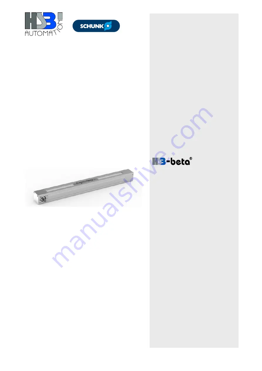
Linear Unit
Type
Beta 60-ZSE
Beta 80-ZSE
Beta 110-ZSE
Summary of Contents for Beta 110-ZSE
Page 2: ......


