background image

©

2007 Matsushita Electric Industrial Co., Ltd. All

rights

reserved.

Unauthorized

copying

and

distribution is a violation of law.

Colour
(S)....................Silver Type

DVD Burner

ORDER NO.VO0708003CE

B27

Summary of Contents for VW-BN1E

Page 1: ... 2007 Matsushita Electric Industrial Co Ltd All rights reserved Unauthorized copying and distribution is a violation of law Colour S Silver Type DVD Burner ORDER NO VO0708003CE B27 ...

Page 2: ...s and Equipment 10 7 Disassembly and Assembly Instructions 11 7 1 Disassembly Flow Chart 11 7 2 Disassembly Procedures 11 8 Measurements and Adjustments 12 8 1 Service Positions 12 9 Block Diagrams 13 9 1 OVERALL BLOCK DIAGRAM 13 10 Schematic Diagrams 15 10 1 MAIN SCHEMATIC DIAGRAM 15 10 2 SUB SCHEMATIC DIAGRAM 16 11 Printed Circuit Board 17 11 1 MAIN P C B 17 11 2 SUB P C B 19 12 Appendix Infomat...

Page 3: ... of AC Adaptor whose chassis is not isolated from the AC power line Use a transformer of adequate power rating as this protects the technician from accidents resulting in personal injury from electrical shocks It will also protect AC Adaptor from being damaged by accidental shorting that may occur during servicing 3 When servicing observe the original lead dress It a short circuit is found replace...

Page 4: ...y 3 Use only a grounded tip soldering iron to solder or unsolder ES devices 4 Use only an antistatic solder removal device Some solder removal devices not classified as antistatic ESD protected can generate electrical charge sufficient to damage ES devices 5 Do not use freon propelled chemicals These can generate electrical charges sufficient to damage ES devices 6 Do not remove a replacement ES d...

Page 5: ...2 2 Precautiopn of Laser Diode 5 VW BN1PP VW BN1E VW BN1GK ...

Page 6: ...lder PbF The lead free solder has to be used when repairing the equipment for which the lead free solder is used Definition The letter of PbF is printed on the PCB using the lead free solder To put lead free solder it should be well molten and mixed with the original lead free solder Remove the remaining lead free solder on the PCB cleanly for soldering of the new IC Since the melting point of the...

Page 7: ...llow service personnel s to understand and service this model Please place orders using the parts list and not the drawing reference numbers If the circuit is changed or modified this information will be followed by supplement service manual to be filed with original service manual 7 VW BN1PP VW BN1E VW BN1GK ...

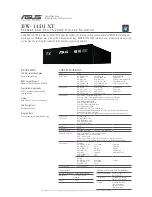
Page 8: ...4 Specifications 8 VW BN1PP VW BN1E VW BN1GK ...

Page 9: ...5 Location of Controls and Components 9 VW BN1PP VW BN1E VW BN1GK ...

Page 10: ...6 Service Fixture Tools 6 1 Service Tools and Equipment 10 VW BN1PP VW BN1E VW BN1GK ...

Page 11: ...everse order 7 2 Disassembly Procedures Flow Chart for Disassembly Procedure No Item Parts Fig Removal Screw Connector Flex Other 1 Rear Case Unit Fig D1 2 Screws A Rear Case Unit 2 Body Case Fig D2 4 Screws B Body Case 3 Sub P C B and Main P C B Fig D3 2 Connectors B2 B3 Sub P C B 3 Screws C Main P C B Fig D1 Fig D2 Fig D3 7 Disassembly and Assembly Instructions 11 VW BN1PP VW BN1E VW BN1GK ...

Page 12: ...ervice Positions 8 1 1 List of the extension cables Use the following extension cables when checking individual circuit boards 8 1 2 Checking and repairing individual circuit boards How to use extension cables 12 VW BN1PP VW BN1E VW BN1GK ...

Page 13: ... 42 IC4002 USB ATAPI BRIDGE 59 19 8 IC4002 3 26 39 58 A2 5V IC4002 11 15 IC4002 7 24 41 54 IC4003 5 20 21 30 31 32 SDA 60 SCL 61 CD DVD OPTICAL PICK UP FEP FRONT END PROCESSOR LASER DIODE DRIVE LDD RF BLOCK SERVO BLOCK THERMISTOR DETECTOR LASER DETECTOR LASER MOTOR SPINDLE MOTOR DRIVE SPINDLE ACTUATOR MOTOR DRIVE LOADING SUPER OPTICAL DISC CONTROLLER SODC DVD DRIVE UNIT DRAM CONTROLLER DRC ADSC SE...

Page 14: ...VW BN1PP VW BN1E VW BN1GK 14 ...

Page 15: ...IFIED PARTS TO B2 SUB P C B IC4002 C1DB00001373 USB ATA BRIDGE 12 11 10 9 8 7 6 5 4 3 2 1 E D F G H C B A VW BN1PP E GK MAIN SCHEMATIC DIAGRAM NOTE FOR SCHEMATIC DIAGRAM AND CIRCUIT BOARD LAYOUT NOTES REFER TO BEGINNING OF SCHEMATIC SECTION NOTE For placing a purchase order of the parts be sure to use the part number listed in the parts list Do not use the part number on this diagram VW BN1PP VW B...

Page 16: ...BN1PP E GK SUB SCHEMATIC DIAGRAM NOTE FOR SCHEMATIC DIAGRAM AND CIRCUIT BOARD LAYOUT NOTES REFER TO BEGINNING OF SCHEMATIC SECTION NOTE For placing a purchase order of the parts be sure to use the part number listed in the parts list Do not use the part number on this diagram VW BN1PP VW BN1E VW BN1GK 16 ...

Page 17: ...11 Printed Circuit Board 11 1 MAIN P C B VW BN1PP E GK MAIN P C B FOIL SIDE COMPONENT SIDE 1 2 3 4 5 6 A B C D LSEP8427A1 VW BN1PP VW BN1E VW BN1GK 17 ...

Page 18: ...UT SHOWS COMPONENTS INSTALLED FOR VARIOUS MODELS FOR PROPER PARTS CONTENT FOR THE MODEL YOU ARE SERVICING PLEASE REFER TO THE SCHEMATIC DIAGRAM AND PARTS LIST NOTE CIRCUIT BOARD LAYOUT INCLUDES COMPONENTS WHICH ARE NOT USED NOTE FOR SCHEMATIC DIAGRAM AND CIRCUIT BOARD LAYOUT NOTES REFER TO BEGINNING OF SCHEMATIC SECTION IMPORTANT SAFETY NOTICE COMPONENTS IDENTIFIED BY THE SIGN HAVE SPECIAL CHARACT...

Page 19: ...ERNS ARE SINGLE PATTERN FOR EACH SIDE THAT MAKE EASY TO SIGHT THE COMPONENT LAYOUT NOTE CIRCUIT BOARD LAYOUT SHOWS COMPONENTS INSTALLED FOR VARIOUS MODELS FOR PROPER PARTS CONTENT FOR THE MODEL YOU ARE SERVICING PLEASE REFER TO THE SCHEMATIC DIAGRAM AND PARTS LIST NOTE CIRCUIT BOARD LAYOUT INCLUDES COMPONENTS WHICH ARE NOT USED NOTE FOR SCHEMATIC DIAGRAM AND CIRCUIT BOARD LAYOUT NOTES REFER TO BEG...

Page 20: ...VW BN1PP VW BN1E VW BN1GK 20 ...

Page 21: ... 17 18 19 20 POWER ON 0 1 2 2 5 0 0 8 0 9 3 3 0 7 0 0 2 5 0 0 0 2 5 0 0 0 3 0 3 0 3 Ref No MODE 21 22 23 24 25 26 27 28 29 30 31 32 33 34 35 36 37 38 39 40 POWER ON 0 4 0 3 0 3 3 0 2 5 1 3 3 3 1 1 1 1 0 0 0 0 0 0 0 0 2 5 0 Ref No MODE 41 42 43 44 45 46 47 48 49 50 51 52 53 54 55 56 57 58 59 60 POWER ON 3 3 0 0 0 0 0 0 0 0 0 0 0 0 5 3 0 2 4 3 3 0 Ref No MODE 61 62 63 64 POWER ON 3 3 3 3 0 0 Ref No ...

Page 22: ...13 Parts and Exploded Views 13 1 Exploded Views 13 1 1 Frame Casing Section 22 VW BN1PP VW BN1E VW BN1GK ...

Page 23: ...13 1 2 Packing Accessories Section 23 VW BN1PP VW BN1E VW BN1GK ...

Page 24: ...2 ECJ2FB0J475K C CAPACITOR CH 6 3V 4 7U 1 C4004 ECJ0EB1A104K C CAPACITOR CH 10V 0 1U 1 C4005 ECJ0EB1A104K C CAPACITOR CH 10V 0 1U 1 C4006 ECJ0EB1A104K C CAPACITOR CH 10V 0 1U 1 Ref No Part No Part Name Description Pcs Remarks C4007 ECJ0EB1C103K C CAPACITOR CH 16V 0 01U 1 C4008 ECJ0EB1C103K C CAPACITOR CH 16V 0 01U 1 C4009 ECJ0EC1H080D C CAPACITOR CH 50V 8P 1 C4010 ECJ0EB1C103K C CAPACITOR CH 16V 0...

Page 25: ...48 ERJ2GEJ470X M RESISTOR CH 1 16W 47 1 R4049 ERJ2GEJ470X M RESISTOR CH 1 16W 47 1 Ref No Part No Part Name Description Pcs Remarks R4050 ERJ2GEJ470X M RESISTOR CH 1 16W 47 1 R4051 ERJ2GEJ470X M RESISTOR CH 1 16W 47 1 R4052 ERJ2GEJ470X M RESISTOR CH 1 16W 47 1 R4053 ERJ2GEJ470X M RESISTOR CH 1 16W 47 1 R4054 ERJ2GEJ470X M RESISTOR CH 1 16W 47 1 R4055 ERJ2GEJ470X M RESISTOR CH 1 16W 47 1 R4056 ERJ2...

Page 26: ...POLYETHYLENE BAG 1 PP E B1 XQN2 BJ4FN SCREW 1 B2 LSHD0137 SCREW 1 B3 LSHD0137 SCREW 1 B4 LSHD0137 SCREW 1 B5 LSHD0137 SCREW 1 B6 LSHD0141 SCREW 1 B7 LSHD0141 SCREW 1 B8 LSHD0141 SCREW 1 B9 LSHD0140 SCREW 1 B10 LSHD0138 SCREW 1 B11 LSHD0138 SCREW 1 B12 LSHD0139 SCREW 1 B13 LSHD0139 SCREW 1 B14 LSHD0139 SCREW 1 B15 LSHD0139 SCREW 1 26 VW BN1PP VW BN1E VW BN1GK ...

Reviews: