Installation and Wiring
16
§
6
6
.
.
1
1
.
.
3
3
I
I
n
n
s
s
t
t
a
a
l
l
l
l
i
i
n
n
g
g
U
U
P
P
S
S
H
H
o
o
r
r
i
i
z
z
o
o
n
n
t
t
a
a
l
l
l
l
y
y
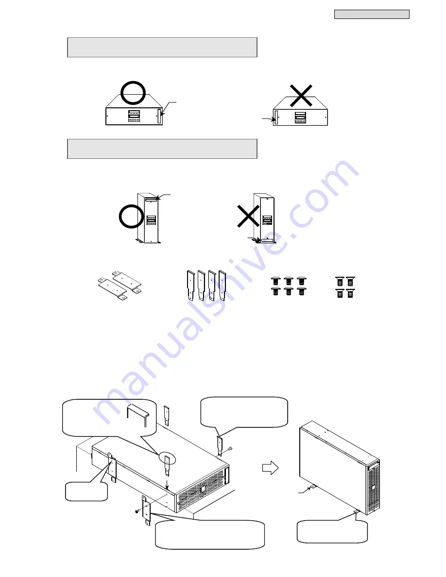
Place the UPS horizontally in the installation location so that the Unit Control Panel on the front of the
UPS is on the right side. Do not place objects on top of the UPS. Doing so may damage the UPS.
§
6
6
.
.
1
1
.
.
4
4
I
I
n
n
s
s
t
t
a
a
l
l
l
l
i
i
n
n
g
g
U
U
P
P
S
S
V
V
e
e
r
r
t
t
i
i
c
c
a
a
l
l
l
l
y
y
When installing the UPS vertically, attach two supplied floor-mounting brackets.
Be sure to place the UPS so that the Unit Control Panel on the front of the UPS is at the top.
①
Prepare two floor-mounting brackets, four support brackets A, six screws A (black), and four screws B
that are supplied with the UPS.
②
Place the UPS horizontally on a table or other surface.
③
Insert the support brackets A in four places on the left and right sides of the UPS so that the tabs at the
top are facing the sides of the UPS.
④
Align the floor-mounting brackets with the mounting holes on the left side, and secure them with two
screws B.
⑤
Secure the support brackets A on the right side with three screws A.
⑥
Check that the brackets are firmly secured.
⑦
Place the UPS upright with the floor-mounting brackets facing downward in the installation location.
⑧
For safety, we recommend securing the UPS to the floor with bolts or the like.
④
Attach each of the floor-mounting
brackets and support brackets A in
two places on the left side with two
screws B.
Screw A (black)
M4×6 6
Floor-mounting Bracket 2
Unit Control Panel
Unit Control Panel
Support Bracket A 4
(Bracket with 3 mounting holes)
③
Insert the support
brackets A in four
places so that the
tabs are facing the
sides of the UPS.
⑧
Secure the UPS to
the floor with bolts or
the like.
⑤
Secure each of the support
brackets in two places on
the right side with three
screws A (black).
Screw B
M4×8 4
Bracket in
attached state
Unit Control Panel
Unit Control Panel
4-
φ
10
Summary of Contents for SANUPS A11J
Page 1: ...M0009237 5 kVA Instruction Manual ...
Page 25: ...Installation and Wiring 22 Blank page ...
Page 41: ...Troubleshooting 38 Blank page ...
Page 50: ...Blank page ...
Page 51: ...Blank page ...
Page 52: ......


