Installation and Wiring
18
⑤
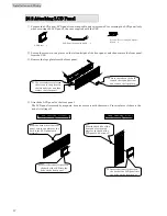
Insert one end of the LCD panel connection cable into the connector at the position shown in the
diagram.
⑥
Check that the forced bypass switch
Forced Bypass
above the connector is set to the “
Inverter
” side.
⑦
Insert the other end of the cable connected in step
⑤
into the connector on the back of the front panel.
⑧
Secure the front panel with screws in two places on the left and right.
Back of Front Panel
⑥
Is the switch set to the
“
Inverter
” side?
⑦
Check the insertion orientation of
the connector.
The connector cannot be inserted
if it is not oriented properly.
⑧
Use a screwdriver to
tighten the screws in two
places on the left and right
to secure the front panel.
⑤
Insert one end of the
connection cable into
the connector.
Summary of Contents for SANUPS A11J
Page 1: ...M0009237 5 kVA Instruction Manual ...
Page 25: ...Installation and Wiring 22 Blank page ...
Page 41: ...Troubleshooting 38 Blank page ...
Page 50: ...Blank page ...
Page 51: ...Blank page ...
Page 52: ......


