background image

V21 Parts & Service Manual


All V21 Identified Equipment


REV A – 10/2013 

P/N: 1230476 


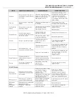
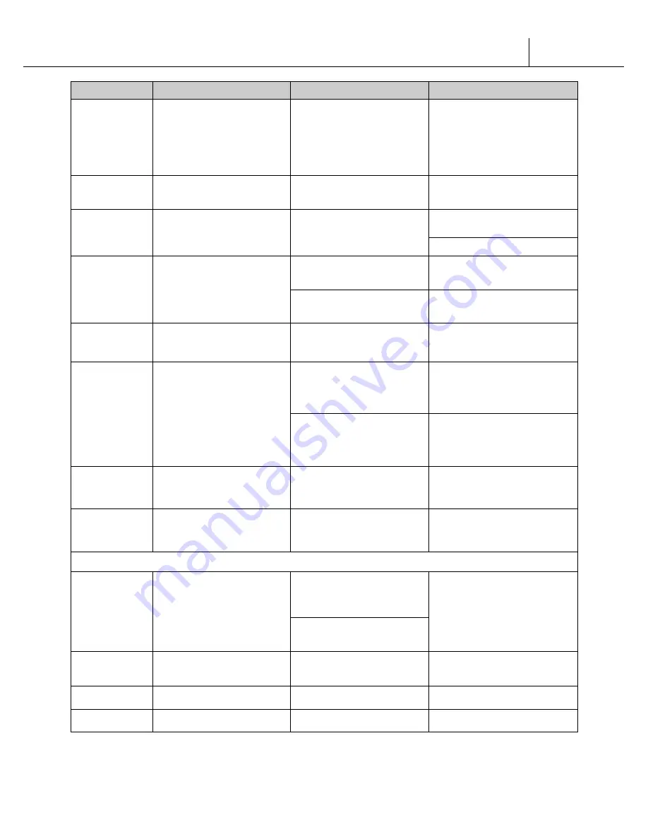
ERROR 

DESCRIPTION OF ERROR CODE 

CHECKING METHOD 

CORRECTIVE ACTION 

Coin Inlet 

Changer inlet chute blocked - no 
coins sensed for over 96 hours by 
the changer. 

Check inlet chute for blockage.  
Drop coins in Sales Mode or Tube 
Fill Mode to test acceptance.  
Manually clear the error. 

Clear inlet chute blockage.  If no 
blockage found, replace changer. If 
acceptance rate is acceptable, 
system is OK.  If acceptance rate is 
low or changer will not accept coins, 
replace changer. 

Tube Jam 

Tube pay out jam -- reported by 
changer. 

Check changer tubes and payout 
for blockage. 

Clear blockage, if found. If no 
blockage is found, replace changer. 

Coin Read Only 
Memory 

Changer check sum incorrect -- 
reported by changer. 

Unplug machine, wait at least five 
seconds, replug machine. 
Manually clear the error. 

If error does not clear, replace 
changer/acceptor. 

Replace acceptor. 

Excessive Escrow 

Excessive escrow requests -- 
more than 255 requests since the 
last coin was sensed. 

Check escrow lever and 
associated mechanisms. 

Manually clear the lever and error. 

Close door then reopen.  Check 
to see if error still occurs. 

Replace changer/acceptor. 

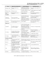
Coin Jam 

Coin jam - reported by changer. 

Check changer/acceptor for 
jammed coins or other 
obstructions. 

If no obstructions are apparent, 
replace changer/acceptor. 

Low Acceptance 

Low acceptance rate -- coin 
acceptance has fallen below 80%. 

Check changer/acceptor for 
obstructions or dirt. 

If no obstructions are apparent, and 
acceptance appears to be OK, this 
may be an indication of cheating 
attempts. 

Drop coins to test acceptance. 

If no obstructions are apparent and 
coins do not accept, or acceptance 
rate is poor, replace 
changer/acceptor. 

Accept Disconnect 

Disconnected acceptor -- 
indicates that an acceptor is 
unplugged. 

Check coin mechanism plugs.  
Check for faulty harness wiring 
(see wiring diagram for circuit). 

Correct connections. 

Routing 

Coin routing - indicates a coin 
was routed incorrectly. 

Verify changer set-up using 
manufacturer's 
recommendations. 

If acceptor was set up correctly, 
replace acceptor. 

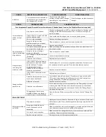
Dollar Bill Acceptor 

Bill Acceptor 
Communication 

Bill acceptor communications - 
No bill acceptor communication 
for 5 seconds. 

If changer or card reader is being 
used, check for “Changer 
Communication” or “Rom 
Checksum” errors. 

If there are no “Changer 
Communication” or “Rom 
Checksum” errors: 1) Check bill 
acceptor harness; 2) Replace bill 
acceptor. If there are those errors: 1) 
Check control board MDB harness. 

Unplug service cord. Wait at least 
5 seconds. Plug in service cord. 
Manually clear the error. 

Bill Acceptor Full 

Bill acceptor full - reported by 
acceptor (STACKER command). 

Insure bill cashbox is empty and 
that the cashbox is properly 
closed and in place. 

If cashbox appears to be OK, replace 
bill acceptor. 

Bill Acceptor 
Motor 

Bill acceptor motor is reported as 
defective by acceptor. 

No test available. 

Replace bill acceptor. 

Bill Acceptor 
Jammed 

Bill jammed -- reported by 
acceptor. 

Check bill acceptor for 
obstructions or dirt. 

If no obstructions are apparent, 
replace bill acceptor. 


V21 T

roubleshooting Chameleon / Trade / HV3 | T1-13 


Summary of Contents for V21 521

Page 1: ...0710 Sanden Drive Dallas TX 75238 T 800 344 7216 F 800 541 5684 T 214 765 9066 F 214 340 8029 www vendoco com FOR TECHNICAL ASSISTANCE PLEASE CALL 1 800 344 7216 EXT 1036 Parts Service Manual For ALL...

Page 2: ...INSTALLATION HV3 Page G 7 LABEL INSTALLATION HVV Page G 8 ALIGNMENT CHECKS Page G 9 LOADING INSTRUCTIONS Pages G 10 G 11 VEND MECHANISM PARTS DESCRIPTION Pages G 12 G 13 VEND CYCLE Pages G 14 G 15 12...

Page 3: ...ARTS CHAMELEON Pages D1 1 D1 10 OUTER DOOR Pages D1 2 D1 7 LOCK ASSEMBLY Page D1 8 INNER DOOR ASSEMBLY Pages D1 9 D1 10 DOOR PARTS CHAMELEON ADA Pages D2 1 D2 8 OUTER DOOR Pages D2 2 D2 5 LOCK ASSEMBL...

Page 4: ...OPTION Pages D8 12 D8 13 INNER DOOR ASSEMBLY Pages D8 14 D8 15 DOOR PARTS HVV ADA Pages D9 1 D9 15 MAIN DOOR Pages D9 2 D9 5 LIGHTING Pages D9 6 D9 9 SELECTION PANEL Pages D9 10 D9 11 T HANDLE OPTION...

Page 5: ...V21 Parts Service Manual All V21 Identified Equipment REV A 10 2013 P N 1230239 SAFETY V21 Safety S 1...

Page 6: ...ram Use these precautions along with the service manual when installing or servicing the vendor We strongly recommend a similar commitment to safety by every servicing organization Only properly train...

Page 7: ...irregularities on the floor surface Ideally no adjustment will be necessary and the leveling legs will be flush with the bottom of the vendor A spirit level is a useful aid to level the vendor When t...

Page 8: ...V21 Parts Service Manual All V21 Identified Equipment REV A 10 2013 P N 1230239 V21 Safety S 4...

Page 9: ...onnect one probe to the receptacle s earth contact B Connect the second probe to the left or upper power contact If a reaction occurs this is the live power contact If a reaction does not occur move t...

Page 10: ...Alignment Figure 3 After any door adjustment the floating quicker lock assembly should align itself automatically The latch assembly is adjustable To adjust loosen the latch bracket mounting screws ra...

Page 11: ...Keep all protective covers and ground wires in place Plug equipment into outlets that are properly grounded and polarized where applicable and protected with fuses or circuit breakers All electrical c...

Page 12: ...lies that combine electrical power and mechanical movement Sudden movement to escape mechanical action can result in contact with live circuits and vice versa It is therefore doubly important to maint...

Page 13: ...ed by qualified personnel Refer to and heed the warnings noted in the electrical hazards section These warnings refer to the potential hazards associated with electrical power and moving parts Always...

Page 14: ...n is required when performing maintenance tests or repairs All testing of sealed refrigeration systems must be done by trained personnel who are familiar with the systems and pressures involved B Phys...

Page 15: ...their original condition A Service Cord Replacement SandenVendo America Inc vending machines are furnished with unique power supply cords If replacement becomes necessary consult the appropriate parts...

Page 16: ...ECTION VII SUBSTITUTIONS AND MODIFICATIONS CONTINUED The wires in the main leads are colored in accordance with the following code 110v 120v 220v 240v Green Green and Yellow Earth White Blue Neutral B...

Page 17: ...nding machine a decal has been designed to be affixed to vending machines One such decal is applied on the vending machine SandenVendo America Inc will supply sufficient decals to be placed on all mac...

Page 18: ...Indonesia Philippines India Sanden International Singapore Pte Ltd Sanden House 25 Ang Mo Kio St 65 Singapore 569062 The Republic of Singapore Tel 65 482 5500 Fax 65 482 1697 Taiwan Sanden Internatio...

Page 19: ...x 52 427 2718077 Mexico IMI Cornelius de Mexico S A de C V Manual Dublan No 35 Col Tacubaya Deleg Miguel Hidalgo C P 11870 Mexico Tel 52 55 5272 7904 Fax 52 55 5273 5949 Central America SandenVendo Am...

Page 20: ...V21 Parts Service Manual All V21 Identified Equipment REV A 10 2013 P N 1230247 V21 General Information G 1 GENERAL INFORMATION...

Page 21: ...X WIDTH X DEPTH CURVED DOOR 61 x 29 x 24 N A 72 X 39 5 X 35 79 X 39 5 X 35 FLAT DOOR N A 72 X 32 5 X 34 5 72 X 39 5 X 32 5 N A SINGLE COLUMNS 7 8 10 10 CAPACITY PER COLUMN 12oz CAN 16oz GLASS 20oz PET...

Page 22: ...OBSTRUCTION This is for proper air flow through the refrigeration compartment The refrigeration system requires rear to front air circulation for proper operation C POWER SUPPLY CONNECTION CAUTION DO...

Page 23: ...e is located on the top left hand corner of the serial plate Do Not use the BASIC UNIT number The BASIC UNIT number is the cabinet size which is used on a number of different machines A typical model...

Page 24: ...INSTRUCTION LABEL Refer to Figure 2 for the following information The coin insert shows the validator opening built into the coin insert Apply instruction label to area shown as needed by the vendor F...

Page 25: ...eparate validator opening and insert B shows the validator opening built into the coin insert Apply instruction label to area shown as needed by the vendor FLAVOR LABELS INSTALLATION In Figure 6 corre...

Page 26: ...l and apply with firm even pressure INSTRUCTION LABEL Refer to Figure 7 for the following information The coin insert shows the validator opening built into the coin insert Apply instruction label to...

Page 27: ...Press the label in near the two upper tabs until the tabs snap into the slots in the upper wall of the selection button See Figure 9 Note if vendor is equipped with optional sold out ready to vend ind...

Page 28: ...will prevent warm moist air from reaching the evaporator area LOADING INSTRUCTIONS BASIC LOAD SET UP see Figure 11 on next page The V21 machine is capable of vending a variety of products For specific...

Page 29: ...V21 Parts Service Manual All V21 Identified Equipment REV A 10 2013 P N 1230247 V21 General Information G 10...

Page 30: ...V21 Parts Service Manual All V21 Identified Equipment REV A 10 2013 P N 1230247 V21 General Information G 11 FOR V21 MODEL 521...

Page 31: ...o a means to provide feedback to the controller to determine when the motor has reached maximum clockwise and counterclockwise positions GATE The gate holds product above the vend bucket GATE LINK The...

Page 32: ...V21 Parts Service Manual All V21 Identified Equipment REV A 10 2013 P N 1230247 V21 General Information G 13...

Page 33: ...t is then reloaded The sequence of these operations changes slightly when the column s depth setting is changed With the single depth setting one purchase is made and the bucket is reloaded With the d...

Page 34: ...V21 Parts Service Manual All V21 Identified Equipment REV A 10 2013 P N 1230247 V21 General Information G 15...

Page 35: ...V21 Parts Service Manual All V21 Identified Equipment REV A 10 2013 P N 1230255 PROGRAMMING SECTION 12 4 PROGRAMMING HV3 CHAMELEON V21 12 4 Programming HV3 CHAMELEON P1 1...

Page 36: ...e door Locate the Mode Button on the Main Control Board and press until Diagnostics appears Use selection button 2 or 3 to navigate through the modes The Modes are as follows Diagnostics Coin Payout T...

Page 37: ...switches display refrigeration system lights and heater Vending a Column 1 At Test Mode press Button 4 Display will read Test Mode Vending 2 Press Button 4 to enter the display will read Column 1 3 Pr...

Page 38: ...utton 4 2 Press Button 2 or 3 to scroll until display reads Test Mode Relays 3 Press Button 4 4 Press Button 2 or 3 to advance through sub modes 5 Press Button 4 at Compressor prompt to test compresso...

Page 39: ...When Discount Counter is displayed press Button 4 to view total discount vend sales 2 Press Button 2 or 3 to display discount counter for individual selections 3 Press Button 1 to exit mode Free Count...

Page 40: ...modes OFF Clock settings and its associated modes are hidden Door Summary ON Sales and cash data are displayed as soon as the outer door is opened or by activating the door switch OFF Sales and cash...

Page 41: ...Indicator ON A small symbol will appear in the lower right hand corner of the display when at least one column is sold out or the machine detects an error OFF The symbol will not appear Count by Selec...

Page 42: ...ton 1 Display reads Save 8 Press Button 4 to save 9 Press Button 1 to exit the mode Set Program Password Allows the operator to set a password to access Sales Data when the door is closed Please note...

Page 43: ...ss Button 4 at Start Day 1 or Start Day 2 4 Scroll through the days of the week or all with Button 2 or 3 5 Press Button 4 to change current setting 6 Change setting by pressing Button 2 or 3 7 Press...

Page 44: ...d Fan X with the current setting displayed 4 To change the setting press Button 4 and the current Fan mode will begin to flash 5 Press Button 2 or 3 to increase or decrease the Fan mode 6 Press Button...

Page 45: ...ress Button 4 when the display reads Refrigeration 2 Press Button 2 or 3 until the display reads Periodic Defrost 3 The display will show it on or off 4 Press Button 4 and the setting value will flash...

Page 46: ...from original vend price Override Allows various items to be enabled or disabled depending on the status of an attached override switch Additional override switch is required kit 1124429 Each of the...

Page 47: ...V21 Parts Service Manual All V21 Identified Equipment REV A 10 2013 P N 1230255 V21 12 4 Programming HV3 CHAMELEON P1 13...

Page 48: ...V21 Parts Service Manual All V21 Identified Equipment REV A 10 2013 P N 1230255 V21 12 4 Programming HV3 CHAMELEON P1 14...

Page 49: ...V21 Parts Service Manual All V21 Identified Equipment REV A 10 2013 P N 1230263 12 4 PROGRAMMING COKE CHAMELEON V21 12 4 Programming Coke Chameleon P2 1...

Page 50: ...s until Diagnostics appears Use selection button 2 or 3 to navigate through the modes The Modes are as follows Diagnostics Coin Payout Tube Fill Recycler Payout Recycler Fill Test Mode Password Cash D...

Page 51: ...Press Button 4 to enter into Coin Payout mode 2 Press Button 2 or 3 to scroll to desired denomination 3 Press Button 4 to dispense displayed denomination 4 Press Button 1 to exit mode Tube Fill Allow...

Page 52: ...ill denomination on the recycler please refer to the recycler manual Test Mode Allows you to test vend a column jog a column test selection switches display refrigeration system lights and heater Vend...

Page 53: ...3 to advance through sub modes 4 Press Button 4 at Compressor prompt to test compressor 5 Press Button 4 at Light prompt to test lighting system 6 Press Button 4 at Fan prompt to test evaporator fan...

Page 54: ...iguration mode turned ON 1 When Sales Data is displayed press Button 4 The non re settable historical data is displayed 2 Press Button 2 or 3 to display resettable individual selections 3 Press Button...

Page 55: ...is the minimum amount of change needed in the coin mechanism before the controller displays the Use Exact Change message Accept Value This is the largest denomination of any single form of currency th...

Page 56: ...validator hit the coin return and receive change without first attempting a vend Off The consumer can insert a bill into the validator press the coin return button and receive change Multi Vend On The...

Page 57: ...ith the selection buttons Space to sales can be set by either choosing one of the 10 preset configurations or you can have the option of doing a custom space to sales For space to Sales mapping refer...

Page 58: ...rent language will be displayed 2 To change current language press Button 4 to start language flashing 3 Press Button 2 or 3 to choose a language 4 Press Button 4 to save the language change 5 Press B...

Page 59: ...Stop Time 1 To turn on the light at the allocated time Start Time 2 To turn off the light at the allocated time Stop Time 2 To turn off the light at the allocated time Please note that the Enable opt...

Page 60: ...e compressor turns on Default The fan is turned on all the time Please note that the fan mode 1 and mode 2 is optional and needs a special hardware Periodic Defrost Mode Enables the refrigeration syst...

Page 61: ...5 Press Button 1 to exit To display the temperature 1 Press Button 4 when the display reads Refrigeration 2 Press Button 2 or 3 until the display reads Sensor Reading 3 Press Button 4 and the current...

Page 62: ...it hour When the fan mode 2 is activated through the Service Modes the controller shall turn on off the compressor and evaporator fans based on the following method When the number of vended product p...

Page 63: ...iscount beverages at regular intervals To program the Discount feature you must enter the following information Start Time When the discounting begins Start Day Stop Time When the discounting ends Sto...

Page 64: ...sales time zone Activate EMS System Open the door press the mode switch on the VMC board The display will read Diagnostics 1 Set Timing Feature 1 Press Button 2 to scroll to Configuration 2 Press But...

Page 65: ...V21 Parts Service Manual All V21 Identified Equipment REV A 10 2013 P N 1230263 V21 12 4 Programming Coke Chameleon P2 17...

Page 66: ...V21 Parts Service Manual All V21 Identified Equipment REV A 10 2013 P N 1230263 Figure to show Pre Programmed Space to Sales V21 12 4 Programming Coke Chameleon P2 18...

Page 67: ...V21 Parts Service Manual All V21 Identified Equipment REV A 10 2013 P N 1230298 12 1 PROGRAMMING TRADE V21 12 1 Programming Trade P3 1...

Page 68: ...REV A 10 2013 P N 1230298 All programming of the V21 is done in the service mode as indicated in the following steps below The main service modes are indicated in white text and the sub modes are ind...

Page 69: ...programming is entered any established credit is returned When and if the door is closed the controller will exit the service mode and return to the sales mode MIS Data As soon as the outer door is o...

Page 70: ...he number of that coin stored in the coin mechanism If selection button two is pressed a pay out of the displayed value will be made Coins will continue to pay out as long as that selection button is...

Page 71: ...the display test mode will advance the controller into the Relay test mode which allows the user to test the lights compressor evaporator fans or the heater Upon entry into the relay test mode the di...

Page 72: ...change to read CASh and XXXX XX where XXXX XX is the value of all discounts towards paid sales This total is non resettable and begins when the discount feature is enabled Pressing selection button 1...

Page 73: ...ervice Manual All V21 Identified Equipment REV A 10 2013 P N 1230298 resettable and begins when the free vend override feature is enabled Press selection button 3 to exit the mode V21 12 1 Programming...

Page 74: ...select the configuration options desired Default options are underlined Display Description Meaning FS Force Select Force select enabled y or disabled n bE Bill Escrow Bill Escrow enabled y or disable...

Page 75: ...bel located on the inner door shear panel See figure 3 SPACE TO SALES CONFIGURATIONS SEL STS10 STS9 STS8 STS7 STS6 STS5 STS4 STS3 STS2 STS1 COL COL COL COL COL COL COL COL COL COL 1 1 1 2 1 1 1 2 3 1...

Page 76: ...ls EP 3 Facilities where operating hours are between 9 am till 9 pm ex Retail Stores St 0 1 5 30 If a sensor is present this is the time the light will turn off after an inactivity period Please note...

Page 77: ...YEAr Current Year Example 2002 dAtE Current Date month day Hour Current Time hours minutes dSt Daylight Savings Time CtLC Clock Control SET UP AND CODE DESCRIPTION CONTINUED LitE Lighting Control Mod...

Page 78: ...tNP for temperature To view the temperature press selection button two To change the degree scale press selection button two when the display reads ForC for Fahrenheit or Celsius To change the curren...

Page 79: ...wo while any of the settings are displayed will enter you in to the refrigeration control settings Pressing selection button one will toggle you through the options Pressing selection button three wil...

Page 80: ...toggle between the following modes SET UP AND CODE DESCRIPTION CONTINUED BLOCK SELECTION OPTIONS CtL1 Controls blocking option SbL1 Set selection buttons y assigned n not assigned Str1 Set time for ma...

Page 81: ...Over Ride Mode Units equipped with optional key switch This feature is used to allow you to manually over ride via a key switch pricing blocking low energy operation and discounting If selection butt...

Page 82: ...pt Y Enable selection blocking N Disable selection blocking SET UP AND CODE DESCRIPTION CONTINUED Litn Over Ride Lighting If selection button two is pressed at the Litn prompt the controller will ente...

Page 83: ...n Upon entry into this program the display will show the current setting dSC4 for enable and dSCn for disable Pressing selection button one will toggle between y for enabled and n for disable Pressing...

Page 84: ...V21 Parts Service Manual All V21 Identified Equipment REV A 10 2013 P N 1230298 V21 12 1 Programming Trade P3 18...

Page 85: ...V21 Parts Service Manual All V21 Identified Equipment REV A 10 2013 P N 1230298 V21 12 1 Programming Trade P3 19...

Page 86: ...ified Equipment REV A 10 2013 P N 1230298 NOTE If the outer door is left open for over an hour the lights and compressor will become active In order to over ride this option press the door switch one...

Page 87: ...V21 Parts Service Manual All V21 Identified Equipment REV A 10 2013 P N 1230328 12 3 PROGRAMMING HVV V21 12 3 Programming HVV P4 1...

Page 88: ...ion buttons in top row Escape Exit In order to access Mode functions open the door Locate the Mode Button Press the mode button one time Row 1 will take you through the modes The available modes are D...

Page 89: ...st Mode Allows you to test vend a column jog a column test selection switches display refrigeration system lights and heater Vend Testing At Test Mode press 2 Display will read column X Press 1 to cho...

Page 90: ...ssor evaporator fan lights and heater At Test Mode press 2 Press 1 until display reads Test Mode Relays Press 2 To advance through sub modes press 1 To test compressor press 2 at Compressor prompt Pre...

Page 91: ...you have the option of pricing each selection button at the same vend price or price each selection button independently Press 2 when display reads Set Price Pressing 1 will allow you to choose selec...

Page 92: ...the coin tubes OFF A vend will not be allowed when the correct change light is on and the consumer attempts to use the dollar bill validator Save Credit Timer ON Credit that is established will be dis...

Page 93: ...Reset W DEX ON MIS data will be reset with a DEX read OFF MIS data will not be reset with a DEX read Depth Learning ON The control board will learn the depth setting after one row of product in the c...

Page 94: ...to save and 3 to exit the mode Door Closed Password Allows you to set a password to access Sales Data only when the door is closed Please note that this function will not work if the password is set...

Page 95: ...l timer Press 2 when the display reads Start Time 1 or Start Time 2 Press 2 at Start Time 1 or Start Time 2 Press 2 at Start Day 1 or Start Day 2 Scroll through the days of the week or all with 1 To c...

Page 96: ...and return the display to Refrigeration To change the Fan Energy Savings mode Press 2 when the display reads Refrigeration Press 1 until the display reads Fan The display will read Fan X with the curr...

Page 97: ...he controller should enter the fan mode 1 This causes the controller to work as fan mode 1 without any setting change When the number of vended product per one hour is more than five the controller sh...

Page 98: ...the Discount feature you must enter the following information Start Time When the discounting begins Start Day Stop Time When the discounting ends Stop Day Selections Amount Amount subtracted discount...

Page 99: ...V21 Parts Service Manual All V21 Identified Equipment REV A 10 2013 P N 1230328 12 3 WIRING DIAGRAM V21 12 3 Programming HVV P4 13...

Page 100: ...V21 Parts Service Manual All V21 Identified Equipment REV A 10 2013 P N 1230328 12 3 WIRING DIAGRAM V21 12 3 Programming HVV P4 14...

Page 101: ...V21 Parts Service Manual All V21 Identified Equipment REV A 10 2013 P N 1230336 CABINET PARTS V21 Cabinet Parts C 1...

Page 102: ...a letter in a hexagon Refer to hardware list section or description and part numbers See pages C 3 and C 4 The example below will show how the parts are listed in the parts lists 1 VEND MOTOR ASSEMBLY...

Page 103: ...V21 Parts Service Manual All V21 Identified Equipment REV A 10 2013 P N 1230336 V21 Cabinet Parts C 3...

Page 104: ...V21 Parts Service Manual All V21 Identified Equipment REV A 10 2013 P N 1230336 V21 Cabinet Parts C 4...

Page 105: ...V21 Parts Service Manual All V21 Identified Equipment REV A 10 2013 P N 1230336 AJ V802162 SCR 1 4 20x1 3 4 HX THD CUT AK V802251 SCR 1 4 20x5 8 HX W LOCK WASHER V21 Cabinet Parts C 5...

Page 106: ...V21 Parts Service Manual All V21 Identified Equipment REV A 10 2013 P N 1230336 V21 Cabinet Parts C 6...

Page 107: ...V21 Parts Service Manual All V21 Identified Equipment REV A 10 2013 P N 1230336 V21 Cabinet Parts C 7...

Page 108: ...111988 1111988 17 SIDE DECAL 2 18 TOP HINGE 1 2000805 03 2000805 03 19 BRACKET STACK SUPPORT 2 1148205 1148205 220 AIR DAM KICK PANEL ASSEMBLY 39 1 1126880 AIR DAM KICK PANEL ASSEMBLY 32 1126880 1 AIR...

Page 109: ...V21 Parts Service Manual All V21 Identified Equipment REV A 10 2013 P N 1230336 V21 Cabinet Parts C 9...

Page 110: ...26691 19 DOOR SWITCH 1 323007 20 OVERLAPPING DOOR GUARD 72 1 2001376 OVERLAPPING DOOR GUARD 79 1 2002325 21 SEAL 39 1 1122500 SEAL 32 1 1122500 1 22 VEND CHUTE 39 1 1121926 8 VEND CHUTE 32 1 1123451 2...

Page 111: ...V21 Parts Service Manual All V21 Identified Equipment REV A 10 2013 P N 1230336 V21 Cabinet Parts C 11...

Page 112: ...1 01 1 1123591 02 1 1123591 03 2 MOTOR COVER 1 1183009 1 1123037 1 1125116 1 1125116 3 BACK SPACER ASSEMBLY 7 1183307 8 1123047 1 10 1123047 1 10 1123047 4 MOTOR HARNESS 1 1123050 1 1123050 1 1122918...

Page 113: ...V21 Parts Service Manual All V21 Identified Equipment REV A 10 2013 P N 1230336 V21 Cabinet Parts C 13...

Page 114: ...2814 10 1122814 3 VEND BUCKET 7 1181622 8 1122815 10 1122815 4 CAN CLIP 8 1122856 10 1122856 5 GATE 7 1183242 8 1122818 10 1122818 6 E CLIP GATE 7 1122818 8 V801080 10 V801080 7 GATE LINK 7 1122819 8...

Page 115: ...REFRIGERATION ASSEMBLY ITEM NO DESCRIPTION QTY REQ PART NO 1 ASY REFER R 134a 115VAC 1 1194536 1 ASY REFER R 134a 230VAC 1 1194159 1 Note For individual components please refer to refrigeration system...

Page 116: ...r individual components please refer to refrigeration system part number marked on name plate located on refrigeration system base panel ITEM NO DESCRIPTION QTY REQ PART NO 1 ASY REFER R 134a 115VAC S...

Page 117: ...02 REFRIGERATION ASSEMBLY Note For individual components please refer to refrigeration system part number marked on name plate located on refrigeration system base panel ITEM NO DESCRIPTION QTY REQ PA...

Page 118: ...V21 Parts Service Manual All V21 Identified Equipment REV A 10 2013 P N 1230336 V21 Cabinet Parts C 18...

Page 119: ...128801 1128801 3 CLAMP 1 324099 3 324099 3 4 CORDSET 1 1184889 1124938 1124939 4 CORDSET HVV 1 1124281 5 TRANSFORMER 1 1111201 1121932 6 FUSEHOLDER 1 1128474 1128474 7 0 8 AMP FUSE NOT SHOWN 1 1053864...

Page 120: ...rness 8 Select Connects the vend motors to the door harness X X N A N A 1121067 Selection Harness 6 Select Right Connects the selection buttons to the control board N A N A X X 1121085 Selection Harne...

Page 121: ...board N A X X X 1122609 Upper Lights Harness HVV Connects the upper lights to the lower lights N A X X X 1123320 Lower Lights Harness HVV Connects the lower lights to the ballast N A X X X 1229206 Lig...

Page 122: ...Box N A X N A N A 1217237 Light Harness LED Complete Chameleon Connects the lights to Power Box N A N A X X 1217237 Light Harness LED Complete HVV Connects the lights to Power Box N A X X X 1221033 L...

Page 123: ...V21 Parts Service Manual All V21 Identified Equipment REV A 10 2013 P N 1230344 DOOR PARTS CHAMELEON V21 Door Parts Chameleon D1 1...

Page 124: ...V21 Parts Service Manual All V21 Identified Equipment REV A 10 2013 P N 1230344 V21 Door Parts Chameleon D1 2...

Page 125: ...ND CHAMELEON 1149374 1149374 10 PLASTIC NUT 1073538 1073538 11 SELECTION SWITCH 368299 368299 12 BRACKET SIGN FACE H 13 SUPPORT BRACKET 1 1143486 1 1143486 14 DOOR ROLLER BRACKET 1 1239376 1 1239376 V...

Page 126: ...V21 Parts Service Manual All V21 Identified Equipment REV A 10 2013 P N 1230344 V21 Door Parts Chameleon D1 4...

Page 127: ...1 1143346 D 4 BEZEL COIN RETURN 1 1170855 1 D 5 RAIN GUARD 1 2000848 K 6 PNT MTG BRKT TOP BTM VIS 821 2 1224518 R Y 7 PNT MTG BRKT SIDE VIS 821 2 1224509 R Y 8 SUPPORT BRACKET 1 1143486 9 LENS DISPLA...

Page 128: ...V21 Parts Service Manual All V21 Identified Equipment REV A 10 2013 P N 1230344 V21 Door Parts Chameleon D1 6...

Page 129: ...R BUMPER 2 1036912 2 1036912 10 DELIVERY HOPPER ASSEMBLY 1149325 1 1149325 D K 10 DELIVERY HOPPER ASSEMBLY VIS NA 1 1222353 R Y 11 LAMP 17W T 8 24 3 1130637 3 1130637 LAMP LED 24 2 1237136 2 1237136 1...

Page 130: ...OCK 1 1143402 2 T HANDLE 1 1002392 3 PIN STUD 1 387601 4 LOCK STUD QUICKER LOCK 1 1049724 5 SPRING 1 389691 6 E RING RETAINER 3 388589 7 HEX WASHER 1 387600 8 SPRING HEAVY 1 389691 9 FLAT WASHER 1 387...

Page 131: ...V21 Parts Service Manual All V21 Identified Equipment REV A 10 2013 P N 1230344 V21 Door Parts Chameleon D1 9...

Page 132: ...NNER DOOR HINGE FEMALE 2 1121286 1121286 8 HINGE PIN 1 1172323 1172323 9 REVERSABLE VEND FLAP 1 1013076 1013076 10 INNER DOOR EYELET 1 387273 387273 11 GROMMET 1 388090 388090 12 INNER DOOR LATCH 1 11...

Page 133: ...V21 Parts Service Manual All V21 Identified Equipment REV A 10 2013 P N 1230352 DOOR PARTS CHAMELEON ADA V21 Door Parts Chameleon ADA D2 1...

Page 134: ...V21 Parts Service Manual All V21 Identified Equipment REV A 10 2013 P N 1230352 V21 Door Parts Chameleon ADA D2 2...

Page 135: ...3 1182388 2 1163504 H 13 SUPPORT BRACKET 1 1143486 1 1143486 1 1143486 1 1143486 14 DOOR ROLLER BRACKET 1 1239376 1 1239376 1 1239376 1 1239376 V802196 15 DOOR ROLLER 1 1120388 1 1120388 11 1120388 1...

Page 136: ...V21 Parts Service Manual All V21 Identified Equipment REV A 10 2013 P N 1230352 V21 Door Parts Chameleon ADA D2 4...

Page 137: ...Y HOPPER ASSEMBLY 1 1182509 1 1189115 1 1 1189115 1 1189115 D K 11 LAMP 17W T 8 24 3 1130637 3 1130637 3 1130637 LAMP LED 24 2 2 1237136 2 1237136 2 1237136 12 LAMP 32W T 8 48 2 1130637 5 2 1121173 2...

Page 138: ...143402 2 T HANDLE 1 1002392 3 PIN STUD 1 387601 4 LOCK STUD QUICKER LOCK 1 1049724 5 SPRING 1 389691 6 E RING RETAINER 3 388589 7 HEX WASHER 1 387600 8 SPRING HEAVY 1 389691 9 FLAT WASHER 1 387718 10...

Page 139: ...V21 Parts Service Manual All V21 Identified Equipment REV A 10 2013 P N 1230352 V21 Door Parts Chameleon ADA D2 7...

Page 140: ...OOR HINGE FEMALE 2 1121286 1121286 1121286 1121286 9 HINGE PIN 1 1172323 1172323 1172323 1172323 10 REVERSABLE VEND FLAP 1 1013076 1013076 1013076 1013076 11 INNER DOOR EYELET 1 387273 387273 387273 3...

Page 141: ...V21 Parts Service Manual All V21 Identified Equipment REV A 10 2013 P N 1230379 DOOR PARTS CHAMELEON LIVE DISPLAY V21 Door Parts Chameleon Live Display D3 1...

Page 142: ...V21 Parts Service Manual All V21 Identified Equipment REV A 10 2013 P N 1230379 CHAMELEON LIVE DISPLAY DOOR V21 Door Parts Chameleon Live Display D3 2...

Page 143: ...L LEFT 72 1 1143516 1143516 1 K 7 BEZEL CONSUMER INTERFACE 1 1143346 1143346 D 8 TRIM EYELET CURVE 1 388271 388271 D 9 LIVE DISPLAY ASY SEE PG 6 2 10 BALLAST 1 1127052 1127052 Y 11 DOOR ROLLER BRACKET...

Page 144: ...V21 Parts Service Manual All V21 Identified Equipment REV A 10 2013 P N 1230379 V21 Door Parts Chameleon Live Display D3 4...

Page 145: ...R 1 1182651 1182651 F 9 DOOR BUMPER 2 1036912 1036912 10 DELIVERY HOPPER ASSEMBLY 1 1149325 1149325 D K 11 LAMP 17W T 8 24 2 1130637 1130637 LAMP LED 24 2 1237136 1237136 12 LAMP 32W T 8 48 2 1130637...

Page 146: ...VE DISPLAY ASSEMBLY ITEM NO DESCRIPTION QTY REQ PART NO 1 FRAME ASSEMBLY 1 1147716 2 BACK ASSEMBLY 5 1147728 3 BUTTON ROUND 5 1149374 4 WASHER PLASTIC 5 1073511 5 NUT PLASTIC 5 1073538 6 HOLDER SELECT...

Page 147: ...43402 2 T HANDLE 1 1002392 3 PIN STUD 1 387601 4 LOCK STUD QUICKER LOCK 1 1049724 5 SPRING 1 389691 6 E RING RETAINER 3 388589 7 HEX WASHER 1 387600 8 SPRING HEAVY 1 389691 9 FLAT WASHER 1 387718 10 T...

Page 148: ...V21 Parts Service Manual All V21 Identified Equipment REV A 10 2013 P N 1230379 V21 Door Parts Chameleon Live Display D3 8...

Page 149: ...Y 1 1125262 1125263 8 INNER DOOR HINGE FEMALE 2 1121286 1121286 9 HINGE PIN 1 1172323 1172323 10 REVERSABLE VEND FLAP 1 1013076 1013076 11 INNER DOOR EYELET 1 387273 387273 12 GROMMET 1 388090 388090...

Page 150: ...V21 Parts Service Manual All V21 Identified Equipment REV A 10 2013 P N 1230387 DOOR PARTS TRADE V21 Door Parts Trade D4 1...

Page 151: ...V21 Parts Service Manual All V21 Identified Equipment REV A 10 2013 P N 1230387 V21 Door Parts Trade D4 2...

Page 152: ...IN TUBE 1 1110619 1110619 12 WATER COLLECTION PLATE 1 1110562 1110562 13 DBV PLUG PLATE UPPER 1 1089597 1089597 14 DBV MOUNT PLATE UPPER 1 1089619 1089619 15 DOOR GUARD 1 2010131 2009503 16 RAIN GUARD...

Page 153: ...V21 Parts Service Manual All V21 Identified Equipment REV A 10 2013 P N 1230387 V21 Door Parts Trade D4 4...

Page 154: ...BALLAST 2 3 LAMP 120 277V 50 60HZ 1 1127582 1127582 1127582 16 SHEAR PANEL LOWER SHEAR PANEL UPPER 1 1 1123915 1241672 1238949 1238868 17 HARNESS TIE 3 1088864 1088864 1088864 18 LAMP HOLDER FIXED ME...

Page 155: ...V21 Parts Service Manual All V21 Identified Equipment REV A 10 2013 P N 1230387 V21 Door Parts Trade D4 6...

Page 156: ...058 15 BALLAST 3 4 LAMP 120 277V 50 60HZ 1 1127052 1127052 1127582 16 SHEAR PANEL LOWER SHEAR PANEL UPPER 1 1 1123915 1241672 1238949 1238868 17 HARNESS TIE 3 1088864 1088864 1088864 18 LAMP HOLDER FI...

Page 157: ...V21 Parts Service Manual All V21 Identified Equipment REV A 10 2013 P N 1230387 V21 Door Parts Trade D4 8...

Page 158: ...619 1110619 10 WATER COLLECTION TRAY 1 1110562 1110562 11 DBV PLUG LOWER 1 1089597 1089597 12 DBV MOUNT PLATE UPPER 1 1089619 1089619 13 DBV PLUG PLATE UPPER 1 1089597 1089597 14 RETAINER SIGN FACE 1...

Page 159: ...V21 Parts Service Manual All V21 Identified Equipment REV A 10 2013 P N 1230387 V21 Door Parts Trade D4 10...

Page 160: ...CK 1 1049724 5 SPRING 1 389691 6 E RING RETAINER 3 388589 7 HEX WASHER 1 387600 8 SPRING HEAVY 1 389691 9 FLAT WASHER 1 387718 10 FLANGE 1 1002384 11 VAPOR SEAL 1 388132 12 WASHER 1 2 2 V801023 13 LEV...

Page 161: ...V21 Parts Service Manual All V21 Identified Equipment REV A 10 2013 P N 1230387 V21 Door Parts Trade D4 12...

Page 162: ...HOUSING 8 1006932 10 1006932 9 SELECTION SWITCH 8 368299 10 368299 10 SOLD OUT PLUG 8 1006975 1 10 1006975 1 11 SELECTION PANEL 1 2010183 1 2010158 12 SELECTION HARNESS 1 1117872 1 1111287 13 DISPLAY...

Page 163: ...V21 Parts Service Manual All V21 Identified Equipment REV A 10 2013 P N 1230387 V21 Door Parts Trade D4 14...

Page 164: ...02 1 7 INNER DOOR HINGE FEMALE 2 1121286 1121286 1121286 8 HINGE PIN 1 389192 389192 389192 9 REVERSABLE VEND FLAP 1 1013076 1013076 1013076 10 INNER DOOR EYELET 1 387273 387273 387273 11 GROMMET 1 38...

Page 165: ...V21 Parts Service Manual All V21 Identified Equipment REV A 10 2013 P N 1230395 DOOR PARTS TRADE ADA V21 Door Parts Trade ADA D5 1...

Page 166: ...V21 Parts Service Manual All V21 Identified Equipment REV A 10 2013 P N 1230395 V21 Door Parts Trade ADA D5 2...

Page 167: ...IN TUBE 1 1110619 1110619 12 WATER COLLECTION PLATE 1 1110562 1110562 13 DBV PLUG PLATE UPPER 1 1089619 1089619 14 DBV MOUNT PLATE UPPER 1 1089619 1089619 15 DOOR GUARD 1 2010131 2009503 16 RAIN GUARD...

Page 168: ...V21 Parts Service Manual All V21 Identified Equipment REV A 10 2013 P N 1230395 V21 Door Parts Trade ADA D5 4...

Page 169: ...BALLAST 2 3 LAMP 120 277V 50 60HZ 1 1127582 1127582 1127582 16 SHEAR PANEL LOWER SHEAR PANEL UPPER 1 1 1123915 1241672 1238949 1238868 17 HARNESS TIE 3 1088864 1088864 1088864 18 LAMP HOLDER FIXED ME...

Page 170: ...V21 Parts Service Manual All V21 Identified Equipment REV A 10 2013 P N 1230395 V21 Door Parts Trade ADA D5 6...

Page 171: ...BALLAST 3 4 LAMP 120 277V 50 60HZ 1 1127052 1127052 1127582 16 SHEAR PANEL LOWER SHEAR PANEL UPPER 1 1 1123915 1241672 1238949 1238868 17 HARNESS TIE 3 1088864 1088864 1088864 18 LAMP HOLDER FIXED MED...

Page 172: ...V21 Parts Service Manual All V21 Identified Equipment REV A 10 2013 P N 1230395 V21 Door Parts Trade ADA D5 8...

Page 173: ...1110619 10 WATER COLLECTION TRAY 1 1110562 1110562 11 DBV PLUG LOWER 1 1089597 1089597 12 DBV MOUNT PLATE UPPER 1 1089619 1089619 13 DBV PLUG PLATE UPPER 1 12072234 12072234 14 RETAINER SIGN FACE 1 10...

Page 174: ...V21 Parts Service Manual All V21 Identified Equipment REV A 10 2013 P N 1230395 V21 Door Parts Trade ADA D5 10...

Page 175: ...1 1049724 5 SPRING 1 389691 6 E RING RETAINER 3 388589 7 HEX WASHER 1 387600 8 SPRING HEAVY 1 389691 9 FLAT WASHER 1 387718 10 FLANGE 1 1002384 11 VAPOR SEAL 1 388132 12 WASHER 1 2 2 V801023 13 LEVER...

Page 176: ...V21 Parts Service Manual All V21 Identified Equipment REV A 10 2013 P N 1230395 V21 Door Parts Trade ADA D5 12...

Page 177: ...HOUSING 8 1006932 10 1006932 9 SELECTION SWITCH 8 368299 10 368299 10 SOLD OUT PLUG 8 1006975 1 10 1006975 1 11 SELECTION PANEL 1 2010183 1 2010158 12 SELECTION HARNESS 1 1117872 1 1111287 13 DISPLAY...

Page 178: ...V21 Parts Service Manual All V21 Identified Equipment REV A 10 2013 P N 1230395 V21 Door Parts Trade ADA D5 14...

Page 179: ...1 7 INNER DOOR HINGE FEMALE 2 1121286 1121286 1121286 8 HINGE PIN 1 389192 389192 389192 9 REVERSABLE VEND FLAP 1 1013076 1013076 1013076 10 INNER DOOR EYELET 1 387273 387273 387273 11 GROMMET 1 3880...

Page 180: ...V21 Parts Service Manual All V21 Identified Equipment REV A 10 2013 P N 1230409 DOOR PARTS TRADE LIVE DISPLAY V21 Door Parts Trade Live Display D6 1...

Page 181: ...V21 Parts Service Manual All V21 Identified Equipment REV A 10 2013 P N 1230409 TRADE LIVE DISPLAY DOOR SECTION V21 Door Parts Trade Live Display D6 2...

Page 182: ...8 24 LAMP 24V LED 3 3 1121173 1237136 3 3 3 1121173 1237136 15 PRICE LABEL BRACKET 2 1124885 2 1124894 16 OUTER DOOR SIGN FACE 1 1 17 3 8 FLAT WASHER BOTTOM 2 V801491 2 V801491 18 BUSHING HINGE 2 3880...

Page 183: ...V21 Parts Service Manual All V21 Identified Equipment REV A 10 2013 P N 1230409 V21 Door Parts Trade Live Display D6 4...

Page 184: ...7 1121740 10 BRACKET CONTROLLER 1 1127473 1 1127473 11 UPPER SHEAR PANEL 1 1124883 1 1124945 12 24 LAMP T 8 24 LAMP 24V LED 3 3 1121173 1237136 3 3 3 1121173 1237136 13 LAMP HOLDER FIXED 1 388531 1 3...

Page 185: ...V21 Parts Service Manual All V21 Identified Equipment REV A 10 2013 P N 1230409 V21 Door Parts Trade Live Display D6 6...

Page 186: ...MP LED 24 2 1237136 15 PRICE LABEL BRACKET 2 1124894 16 OUTER DOOR SIGN FACE 1 17 3 8 FLAT WASHER BOTTOM 2 V801491 18 BUSHING HINGE 2 388094 19 DOOR ROLLER BRACKET 1 1120552 20 DOOR ROLLER 1 1120388 2...

Page 187: ...V21 Parts Service Manual All V21 Identified Equipment REV A 10 2013 P N 1230409 V21 Door Parts Trade Live Display D6 8...

Page 188: ...1 1123051 12 1 8 STANDOFF 7 1121740 9 BRACKET CONTROLLER 1 1124644 10 UPPER SHEAR PANEL 1 1124945 11 LAMP 24 T 8 LAMP 24 24V LED 3 3 1121173 1237136 12 LAMP HOLDER FIXED 1 388531 13 LAMP HOLDER BRACKE...

Page 189: ...V21 Parts Service Manual All V21 Identified Equipment REV A 10 2013 P N 1230409 V21 Door Parts Trade Live Display D6 10...

Page 190: ...2 V801023 13 LEVER COIN RETURN 1 1052619 14 CRANK COIN RETURN LEVER 1 1002244 15 PIVOT BRACKET COIN RETURN 1 1002252 16 BUSHING 2 385603 4 17 SPRING COIN RETURN LEVER 1 1060023 18 COIN INSERT PLATE 1...

Page 191: ...V21 Parts Service Manual All V21 Identified Equipment REV A 10 2013 P N 1230409 V21 Door Parts Trade Live Display D6 12...

Page 192: ...EYELET 1 387273 387273 12 GROMMET 1 388090 388090 13 INNER DOOR LATCH 1 1121711 1121711 14 INNER DOOR LATCH BRACKET 1 1121712 1121712 15 INNER DOOR GRAPHICS 1 16 RETAINER GRAPHICS SIDE 1 1125123 2 11...

Page 193: ...V21 Parts Service Manual All V21 Identified Equipment REV A 10 2013 P N 1230417 DOOR PARTS HV3 ADA V21 Door Parts HV3 ADA D7 1...

Page 194: ...V21 Parts Service Manual All V21 Identified Equipment REV A 10 2013 P N 1230417 V21 Door Parts HV3 ADA D7 2...

Page 195: ...10 368299 12 BRACKET SIGN FACE 3 1204888 3 1204888 H 13 SUPPORT BRACKET 1 1143486 1 1143486 14 DOOR ROLLER BRACKET 1 1239376 1 1239376 V802196 15 DOOR ROLLER 1 1120388 1 1120388 V802162 16 BUSHING HIN...

Page 196: ...V21 Parts Service Manual All V21 Identified Equipment REV A 10 2013 P N 1230417 NOTE WHEN ORDERING SIGN FACE PLEASE PROVIDE FRANCHISE AND STYLE V21 Door Parts HV3 ADA D7 4...

Page 197: ...1 1123049 H 6 PLATE DBV PLUG UPPER 1 1143498 1 1143498 F 7 COIN INSERT CHUTE 1 1121066 1 1121066 U 8 ASY COIN RETURN LEVER 1 1182651 1 1182651 F 9 DOOR BUMPER 2 1036912 2 1036912 10 DELIVERY HOPPER AS...

Page 198: ...3402 2 T HANDLE 1 1002392 3 PIN STUD 1 387601 4 LOCK STUD QUICKER LOCK 1 1049724 5 SPRING 1 389691 6 E RING RETAINER 3 388589 7 HEX WASHER 1 387600 8 SPRING HEAVY 1 389691 9 FLAT WASHER 1 387718 10 T...

Page 199: ...V21 Parts Service Manual All V21 Identified Equipment REV A 10 2013 P N 1230417 V21 Door Parts HV3 ADA D7 7...

Page 200: ...LE 2 1121286 1121286 8 HINGE PIN 1 1172323 1172323 9 REVERSABLE VEND FLAP 1 1013076 1013076 10 INNER DOOR EYELET 1 387273 387273 11 GROMMET 1 388090 388090 12 INNER DOOR LATCH 1 1121711 1121711 13 INN...

Page 201: ...V21 Parts Service Manual All V21 Identified Equipment REV A 10 2013 P N 1230425 DOOR PARTS HVV V21 Door Parts HVV D8 1...

Page 202: ...V21 Parts Service Manual All V21 Identified Equipment REV A 10 2013 P N 1230425 V21 Door Parts HVV D8 2...

Page 203: ...1100 1121100 LOWER SIGN TRIM 72 79 GREEN N A 1121100 3 1121100 3 LOWER SIGN TRIM 72 79 BLACK 1121100 6 1121100 6 10 RAIN GUARD BLUE 1 2005937 2005872 2005872 RAIN GUARD GREEN 2005937 1 2005872 01 2005...

Page 204: ...V21 Parts Service Manual All V21 Identified Equipment REV A 10 2013 P N 1230425 V21 Door Parts HVV D8 4...

Page 205: ...DOOR WELD 72 1 1121120 3 DOOR WELD 79 1121120 5 1121120 4 10 LOWER HINGE HOOK 1 1121923 1121923 1121923 11 DOOR BUMPER HEYCO 2551 1 1036912 1036912 1036912 12 LOCK ASSEMBLY HT2 TT 1 1123073 1123073 1...

Page 206: ...V21 Parts Service Manual All V21 Identified Equipment REV A 10 2013 P N 1230425 V21 Door Parts HVV D8 6...

Page 207: ...LED 4 2 1237136 1 2 LAMP T 8 2 2 1121173 LAMP LED 2 2 1237136 3 LAMPHOLDER FIXED 2 388531 4 LAMPHOLDER PLUNGER 2 388532 5 LAMP BRACKET 90 6 1126231B 6 LAMP BRACKET STRAIGHT 2 1126231 2B 7 VERTICAL SUP...

Page 208: ...V21 Parts Service Manual All V21 Identified Equipment REV A 10 2013 P N 1230425 V21 Door Parts HVV D8 8...

Page 209: ...O 1 LAMP T 8 FOR MODEL 721 2 1121030 LAMP T 8 FOR MODEL 821 1119340 2 LAMPHOLDER PLUNGER 2 388532 3 LAMPHOLDER FIXED 2 388531 4 LAMP BRACKET 4 1126231B 5 BALLAST 220V FOR MODEL 721 1 1120450 BALLAST 2...

Page 210: ...V21 Parts Service Manual All V21 Identified Equipment REV A 10 2013 P N 1230425 V21 Door Parts HVV D8 10...

Page 211: ...N A 1122613 21 SOLD OUT READY TO VEND ASSY RIGHT 6 SEL BLACK 2 N A 1122613 22 SOLD OUT READY TO VEND ASSY LEFT 6 SEL BLACK 2 N A 1122613 23 RIGHT PANEL ASSEMBLY 3 SELECTION BLUE 2 1122613 4 N A LEFT...

Page 212: ...V21 Parts Service Manual All V21 Identified Equipment REV A 10 2013 P N 1230425 V21 Door Parts HVV D8 12...

Page 213: ...COVER PLATE BLUE 1 1126568 2 LOCK SHIELD 1 1126218 3 LOCK STUD COVER 1 1121817 1 4 T HANDLE LOCK ASSEMBLY 1 1126557 5 T HANDLE 1 1002392 6 SPRING 1 389691 7 E RING RETAINER 2 388589 8 HEX WASHER 1 38...

Page 214: ...V21 Parts Service Manual All V21 Identified Equipment REV A 10 2013 P N 1230425 V21 Door Parts HVV D8 14...

Page 215: ...1 7 LONG CLIP ASSEMBLY 1 1125262 1125263 8 INNER DOOR HINGE FEMALE 2 1121286 1121286 9 HINGE PIN 1 1172323 1172323 10 REVERSABLE VEND FLAP 1 1013076 1013076 11 INNER DOOR EYELET 1 387273 387273 12 GRO...

Page 216: ...V21 Parts Service Manual All V21 Identified Equipment REV A 10 2013 P N 1230433 DOOR PARTS HVV ADA V21 HVV ADA Trade Door Section D9 1...

Page 217: ...V21 Parts Service Manual All V21 Identified Equipment REV A 10 2013 P N 1230433 V21 HVV ADA Trade Door Section D9 2...

Page 218: ...D BLUE 1 2005937 2005872 2005872 RAIN GUARD GREEN 2005937 1 2005872 01 2005872 01 RAIN GUARD BLACK N A 2000848 2000848 10 DOOR GUARD 72 BLUE 1 1122179 1122179 DOOR GUARD 79 BLUE 1122179 1 DOOR GUARD 7...

Page 219: ...V21 Parts Service Manual All V21 Identified Equipment REV A 10 2013 P N 1230433 V21 HVV ADA Trade Door Section D9 4...

Page 220: ...15 1189115 1189115 9 DOOR BUMPER HEYCO 2551 1 1036912 1036912 1036912 10 LOCK ASSEMBLY HT2 TT 1 1123073 1123073 1123073 11 TRITEQ LOCK LIGHT PIPE SHROUD 1 1123640 1123640 1123640 12 LIGHT PIPE SHIELD...

Page 221: ...V21 Parts Service Manual All V21 Identified Equipment REV A 10 2013 P N 1230433 V21 HVV ADA Trade Door Section D9 6...

Page 222: ...2 LAMP T 8 24 2 1121173 1121173 LAMP LED 24 2 1237136 1237136 3 LAMPHOLDER FIXED 4 1151253 1151253 4 LAMPHOLDER PLUNGER 4 1151265 1151265 5 LAMP BRACKET 90 6 1126231 1126231 6 LAMP BRACKET STRAIGHT 2...

Page 223: ...V21 Parts Service Manual All V21 Identified Equipment REV A 10 2013 P N 1230433 V21 HVV ADA Trade Door Section D9 8...

Page 224: ...LAMP T 8 FOR MODEL 721 2 1121030 LAMP T 8 FOR MODEL 821 1119340 2 LAMPHOLDER PLUNGER 2 388532 3 LAMPHOLDER FIXED 2 388531 4 LAMP BRACKET 4 1126231B 5 BALLAST 220V FOR MODEL 721 1 1120450 BALLAST 220V...

Page 225: ...V21 Parts Service Manual All V21 Identified Equipment REV A 10 2013 P N 1230433 V21 HVV ADA Trade Door Section D9 10...

Page 226: ...1122613 21 SOLD OUT READY TO VEND ASSY RIGHT 6 SEL BLACK 2 N A 1122613 22 SOLD OUT READY TO VEND ASSY LEFT 6 SEL BLACK 2 N A 1122613 23 RIGHT PANEL ASSEMBLY 3 SELECTION BLUE 2 1122613 4 N A LEFT PANE...

Page 227: ...V21 Parts Service Manual All V21 Identified Equipment REV A 10 2013 P N 1230433 V21 HVV ADA Trade Door Section D9 12...

Page 228: ...PLATE BLUE 1 1126568 2 LOCK SHIELD 1 1126218 3 LOCK STUD COVER 1 1121817 1 4 T HANDLE LOCK ASSEMBLY 1 1126557 5 T HANDLE 1 1002392 6 SPRING 1 389691 7 E RING RETAINER 2 388589 8 HEX WASHER 1 387600 9...

Page 229: ...V21 Parts Service Manual All V21 Identified Equipment REV A 10 2013 P N 1230433 V21 HVV ADA Trade Door Section D9 14...

Page 230: ...02 1125202 1125202 1 8 INNER DOOR HINGE FEMALE 2 1121286 1121286 1121286 9 HINGE PIN 1 1172323 1172323 1172323 10 REVERSABLE VEND FLAP 1 1013076 1013076 1013076 11 INNER DOOR EYELET 1 387273 387273 38...

Page 231: ...V21 Parts Service Manual All V21 Identified Equipment REV A 10 2013 P N 1230468 MAINTENANCE V21 Maintenance M 1...

Page 232: ...lace all lamps within 24 to 48 hours of burnout This will prevent damage to the ballast D Check the product temperature for proper cooling E Check the evaporator drain for obstruction water in the eva...

Page 233: ...cratches and minor abrasions by using any good quality automobile polish Test product before using E LEXAN SIGNS To clean Lexan sign faces the following procedure is recommended A Wash sign with mild...

Page 234: ...evaporator to the condenser at the condenser the heat is dissipated into the surrounding air The liquid refrigerant changes from a liquid to a vapor and back to a liquid again This change of state all...

Page 235: ...m the evaporator and compresses it increasing both pressure and temperature The compressor forces the compressed vapor out through the discharge line and into the condenser The condenser fan pulls air...

Page 236: ...V21 Parts Service Manual All V21 Identified Equipment REV A 10 2013 P N 1230468 V21 Maintenance M 6...

Page 237: ...ve strainer drier It removes water and solid particles from refrigerant liquid One side of the drier is connected to the outlet line of the condenser the other side is connected to the capillary tube...

Page 238: ...V21 Parts Service Manual All V21 Identified Equipment REV A 10 2013 P N 1230468 V21 Maintenance M 8...

Page 239: ...arting circuit When the compressor motor reaches operating speed the starting relay opens and breaks the starting circuit THERMAL OVERLOAD SWITCH INCLUDED IN ASSEMBLY P N CHAMELEON 513506066 TRADE 513...

Page 240: ...V21 Parts Service Manual All V21 Identified Equipment REV A 10 2013 P N 1230476 TROUBLESHOOTING V21 Troubleshooting Chameleon Trade HV3 T1 1...

Page 241: ...urn Material Tags will be furnished upon request On site inspection of defective parts at SandenVendo America Inc option may be used to facilitate credit approval or the replacement of parts VII Sande...

Page 242: ...ost inexpensive method of transportation Federal Express Ground or Overnight Transportation SandenVendo can also provide pick up service upon request Please ask your CSR about this option Return packa...

Page 243: ...r clearing a displayed error code either the next existing detailed error code summary level error code or the nonE message will be displayed respectively 9 If selection button three Return is pressed...

Page 244: ...no blockage is found replace changer CrCH Changer check sum incorrect reported by changer Turn power switch off wait at least five seconds then turn on Manually clear the error If error does not clear...

Page 245: ...ceptor is being used check for rC or bC errors If there is no rC or bC error 1 Check changer harness 2 Replace changer Turn power switch off Wait at least ve seconds Turn power switch on If there is a...

Page 246: ...s in the path Clean acceptor or contact dealer Coin changer is improperly tuned if turnable Contact manufacturer for tuning Defective control board Replace test control board Always accepts coins but...

Page 247: ...cal Error Check for correct operation of the motor gate link bucket and gate Wrong product vending upon selection Misload by vendor loader Ensure that all product within each column is the same Space...

Page 248: ...Solid 8888 s on the LED Defective LED Replace LED and or harness Defective control board Replace control board Refrigeration Refrigeration unit will not run even at the speci c temperature No power o...

Page 249: ...Replace the temperature sensor Defective control board Replace the board Poor sealing Check gasket vend ap and permagum on the bulkhead Product freezing up too cold Temperaturesettingtoolow Adjust se...

Page 250: ...compressor test mode on in order to check for voltage Defective door switch Upon opening the door the lights and compressor should shut off If they don t replace the door switch Defective control boa...

Page 251: ...n 15 seconds while in the Customer Mode or Door Open Sales Test Mode Check the selection switch number shown in the detailed error code nn to see if 1 the button is sticking 2 the switch is sticking d...

Page 252: ...ctions or dirt If no obstructions are apparent and acceptance appears to be OK this may be an indication of cheating attempts Drop coins to test acceptance If no obstructions are apparent and coins do...

Page 253: ...trol board is plugged in Not Cooling System has failed to decrease temperature 1 per hour while the compressor is running Access relay mode refer to programming manual Refer to the refrigeration troub...

Page 254: ...T Defective harness between coin mech and control board will have Changer Communication error Check harness for cut wires or wrong bad connections Test each wire for continuity or test to ground If fo...

Page 255: ...ot adjusted correctly Move can clip to proper position refer to loading diagram on machine Mechanical Error Check for correct operation of the motor lock link bucket and gate Wrong product vending upo...

Page 256: ...ol board Vendor accepts and credits money but does not vend does not indicate a sold out Defective selection switch Replace switch Defective selection switch harness Repair or replace harness Defectiv...

Page 257: ...ls Compressor starts but does not run Will not cycle Check overload and contacts Replace if needed Replace Start relay Check replace if needed Starting relay stays closed Compressor motor problem Comp...

Reviews: