S&C Instruction Sheet 766-510
17
Installation
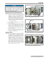
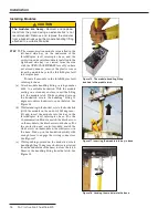
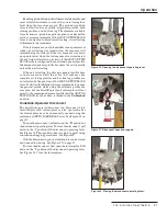
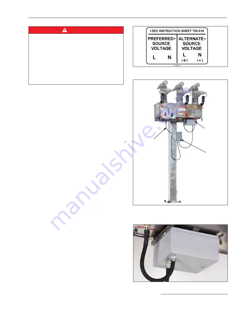
Figure 22. The optional external power supply can be easily
removed.
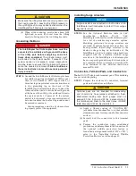
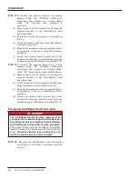
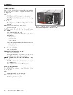
Figure 20. Input power terminals in the user interface box.
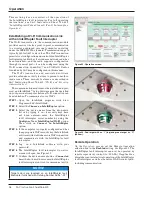
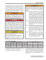
Figure 21. Compact-crossarm IntelliRupter fault interrupter on
substation pedestal with an external power supply and a user
interface box.
External
power supply
External power
supply user
interface box
Optional fiber-optic
connection to
communication
module
DANGER
The interrupters, terminal pads, and
disconnect blades of disconnect style models
may be energized from either side of the
IntelliRupter fault interrupter and with the
interrupters in any position. Before inspecting,
servicing, or repairing an IntelliRupter fault interrupter
or working on the conductors on either side of it, test
for voltage using proper high-voltage test equipment.
Install suitable grounding equipment.
Failure to
observe these precautions can result in serious
personal injury or death.
Substation Power and Communication
External Power Supply
—An external power supply is
an option used when system voltage is below 7.5 kV 60Hz,
9 kV 50Hz, or with a pedestal-mounted IntelliRupter fault
Interrupter in a substation. It enables the use of preferred
and alternate control power sources, and can be installed
in combination with integral power modules. Figure 20
shows the input terminal assignment. For two source
applications, the
Preferred
input provides power to the
IntelliRupter fault interrupter when voltage is present,
and the
Alternate
input takes over when
Preferred
input
voltage is lost. Either input may be used for a single-source
ac application. The voltage ranges for each input are:
Preferred Input
: 100 to 259 Vac, 50/60 Hz
Alternate Input
: 100 to 259 Vac, 50/60 Hz, 20 to 60 Vdc,
or 100 to 360 Vdc.
When operating in the 100- to 360-Vdc range, a minimum
of 100 Vdc is required to power the IntelliRupter fault inter-
rupter from a cold start. When powered the IntelliRupter
fault interrupter remains operational until the
Alternate
input voltage drops to 70 Vdc.
IntelliRupter fault interrupter voltage sensors provide
accurate sensing at voltages as low as 4.13 kV, so using the
external power supply, instead of integral power modules,
expands the IntelliRupter fault interrupter system voltage
range down to this level.
A line person can easily remove the external power
supply with gloved hands because no tools are required to
release the chassis from its mounting plate. See Figure 22.
Also see S&C Instruction Sheet 766-512, ED-850, and
ED-855 for more details.
Fiber-Optic Connection
—The communication
module can be furnished with a factory installed single-
mode or multi-mode fiber-optic modem. A fiber-optic
cable connects the faceplate of the communication
module to the user interface box, where the IntelliRupter
fault interrupter is connected to the fiber-optic network.
See Figure 21.
An IntelliRupter fault interrupter can be easily con-
verted from radio communication to fiber-optic commu-
nication by changing the communication module.

