14
S&C Instruction Sheet 766-510
Installing Modules
CAUTION
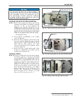
The modules are heavy. Removal and replace-
ment from the ground using an extendostick is not
recommended. Remove and replace the modules
from a bucket truck using the module handling fitting
attached to a suitable hookstick.
STEP 11.
The communication module is installed in the
left-hand side bay, on the underside of the
IntelliRupter fault interrupter base, and the
protection and control module is installed in the
right-hand side bay—as viewed from the side
with the OPEN/CLOSE/READY lever. If you have
not already done so, remove the plastic covers
from the module bays in the IntelliRupter fault
interrupter base.
To install a module in the IntelliRupter fault
interrupter base:
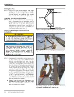
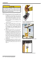
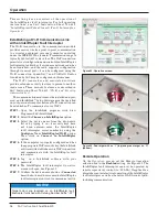
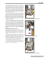
(a) Attach module handling fi tting, catalog number
4450, to a suitable hookstick. With the module
resting on a clean dry surface, insert the fi tting
into the module latch. While pushing down on
the hookstick, rotate the handling fi tting 90
degrees counterclockwise to open the latch. See
Figure 16.
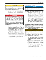
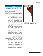
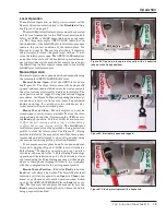
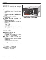
(b) While standing in the bucket, rotate the hookstick
(with the module on the end of it) 180 degrees—
lift and insert the module into the bay in the
IntelliRupter fault interrupter base. For the
Communication Module, match the black arrow
on the module to the black arrow on the base. For
the protection and control module, match the
white arrow on the module to the white arrow on
the base. Push up on the hookstick quickly with
enough force to engage the wiring connectors.
See Figure 17.
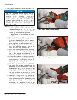
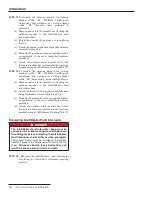
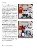
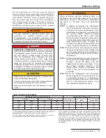
(c) While pushing upward on the hookstick, rotate
handling fi tting 90 degrees clockwise (as viewed
from the underside of the base) to close the latch.
Remove the handling fi tting from the latch. See
Figure 18.
Installation
Figure 18. Locking the module into the base.
Figure 17. Inserting the module into bay in base.
Figure 16. The module-handling fitting
inserted in the module latch.

