
4
S&C Instruction Sheet 766-510
Safety Information
Reorder Information for Safety Information
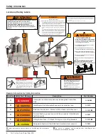
Location Safety Alert Message
Description
Part Number
A
DANGER
Interrupters and terminal pads may be energized from either
side . . .
G-9615
●
B
WARNING
IntelliRupter fault interrupter base contains electrical and . . .
G-9220
C
WARNING
Electrocution Hazard—Failure to follow these instructions can . . .
G-9222
■
D
WARNING
Do not attach any power source to this connector if IntelliRupter
fault interrupter. . .
G-9281
E
WARNING
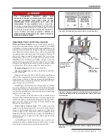
Lifting Instructions—1. Attach lift slings only to lifting brackets . . .
G-9223
■
F
CAUTION
Keep personnel more than 6.56 feet (2 meters) from vacuum . . .
G-9632
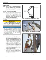
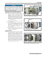
Location of Safety Labels
B
C
WARNING
ELECTROCUTION HAZARD
Failure to follow these instructions can cause serious injury or death.
• This IntelliRupter
®
PulseCloser
®
Fault Interrupter must be installed, grounded
and operated ONLY by qualified personnel familiar with high-voltage electrical
equipment, associated safety practices, and potential hazards.
• Before energization, and at all times when energized, the IntelliRupter fault
interrupter base must be connected to a suitable earth ground at the base
of the pole in accordance with the S&C instruction sheet furnished with this
device.
• The IntelliRupter fault interrupter base ground must also be connected to the
system neutral. If the system neutral is not present, proper precautions must
be taken to ensure that the local earth ground cannot be severed or removed.
• To ensure safe and effective installation and operation, follow procedures
in the S&C instruction sheet furnished with this device EXACTLY.
• For additional S&C instruction sheets, call 1-773-338-1000.
G-9222
REMOVE THIS T
AG
AFTER IntelliRupter
®
fault
interrupter IS INST
ALLED
AND
ADJUSTED.
D
E
A
WARNING
G-9281
DO NOT attach any power source, EXCEPT FOR
S&C EXTERNAL POWER SUPPLY (EPS), to this
connector when IntelliRupter
©
fault interrupter
is energized at high voltage.
Use S&C Power Supply Accessory Catalog Number
TA-3221 ONLY when energizing the IntelliRupter
fault interrupter indoors, in a service center, or
testing lab.
Attaching a power supply of other manufacture may
cause equipment damage or electric shock.
WARNING
G-9220
IntelliRupter fault interrupter base contains electrical
and mechanical parts that can cause injury.
DO NOT disassemble or remove access panels
unless directed by S&C Electric Company.
DO NOT drill into IntelliRupter fault interrupter base.
Damage to internal components can cause equipment
failure.
®
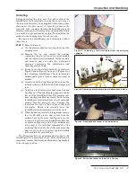
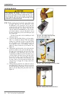
WARNING
G-9223
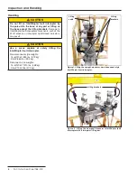
LIFTING INSTRUCTIONS
1. Attach lifting slings
ONLY
to lifting brackets
provided. (Lifting brackets are permanently
attached to the IntelliRupter® PulseCloser®
Faut Interrupter for future use).
2. Lift IntelliRupter fault interrupter as shown
until slings are just taut.
3. Unbolt IntelliRupter fault interrupter from
steel brackets attached to the shipping skid.
4. Slowly and carefully lift IntelliRupter fault
interrupter onto pole or structure.interrupter
5. Securely bolt IntelliRupter fault interrupter
to pole or structure.
6. Remove tie wrap and fold lifting brackets
down.
Failure to lift IntelliRupter fault interrupter
properly can result in damage, causing
improper operation,
arcing,
or electrical
shock
Lifting brackets
CAUTION
Keep personnel more than 6.56 feet (2 meters) from vacuum interrupter during tests.
X-rays can be produced when high voltage withstand test levels are placed across
open contacts.
Exposure to X-radiation can be hazardous to your health.
G-9632
F
●
Label is placed on front and back of IntelliRupter fault interrupter
base.
■
Tag which is removed and discarded after IntelliRupter fault
interrupter is installed and adjusted.
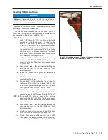
DANGER
Interrupters and terminals pads may be energized
from either side and in position.
ALWAYS consider all parts live until de-energized,
tested, and grounded. To avoid electrical shock, the
IntelliRupter
®
fault interrupter base must be grounded.
The Integral Power Module Capacitors can retain
a charge after being disconnected from the power
system. To discharge the IPM Capacitors connect the
high voltage terminal connected to each IPM to the
IntelliRupter base.
Integral Power
Module Capacitors
G-9615